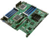
Intel BB5520UR Product Specification - Page 9
Jumper Blocks J1E2, J1E4, J1E5, J1E6, J1H1
 |
View all Intel BB5520UR manuals
Add to My Manuals
Save this manual to your list of manuals |
Page 9 highlights
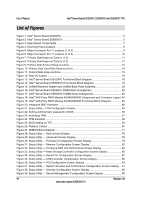
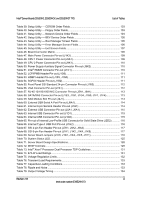
Intel® Server Boards S5520HC, S5500HCV, and S5520HCT TPS List of Figures Figure 40. Setup Utility - Console Redirection Screen Display 96 Figure 41. Setup Utility - Server Management System Information Screen Display 98 Figure 42. Setup Utility - Boot Options Screen Display 99 Figure 43. Setup Utility - Add New Boot Option Screen Display 101 Figure 44. Setup Utility - Delete Boot Option Screen Display 102 Figure 45. Setup Utility - Hard Disk Order Screen Display 102 Figure 46. Setup Utility - CDROM Order Screen Display 103 Figure 47. Setup Utility - Floppy Order Screen Display 103 Figure 48. Setup Utility - Network Device Order Screen Display 104 Figure 49. Setup Utility - BEV Device Order Screen Display 104 Figure 50. Setup Utility - Boot Manager Screen Display 105 Figure 51. Setup Utility - Error Manager Screen Display 106 Figure 52. Setup Utility - Exit Screen Display 106 Figure 53. Jumper Blocks (J1E2, J1E4, J1E5, J1E6, J1H1 118 Figure 54. 5-volt Stand-by Status LED Location 122 Figure 55. Fan Fault LED's Location 123 Figure 56. System Status LED Location 124 Figure 57. DIMM Fault LED's Location 126 Figure 58. POST Code Diagnostic LED Locations 127 Figure 59. Power Distribution Block Diagram 130 Figure 60. Output Voltage Timing 134 Figure 61. Turn On/Off Timing (Power Supply Signals 135 Figure 62. Active Processor Heatsink Installation Requirement 149 Figure 63. Diagnostic LED Placement Diagram 161 Revision 1.8 ix Intel order number E39529-013
-
 1
1 -
2
-
3
-
 4
4 -
 5
5 -
 6
6 -
 7
7 -
 8
8 -
 9
9 -
 10
10 -
 11
11 -
 12
12 -
 13
13 -
 14
14 -
15
-
16
-
17
-
18
-
19
-
20
-
21
-
22
-
23
-
24
-
25
-
26
-
27
-
28
-
29
-
30
-
31
-
32
-
33
-
34
-
35
-
36
-
37
-
38
-
39
-
40
-
41
-
42
-
43
-
44
-
45
-
46
-
47
-
48
-
49
-
50
-
51
-
52
-
53
-
54
-
55
-
56
-
57
-
58
-
59
-
60
-
61
-
62
-
63
-
64
-
65
-
66
-
67
-
68
-
69
-
70
-
71
-
72
-
73
-
74
-
75
-
76
-
77
-
78
-
79
-
80
-
81
-
82
-
83
-
84
-
85
-
86
-
87
-
88
-
89
-
90
-
91
-
92
-
93
-
94
-
95
-
96
-
97
-
98
-
99
-
100
-
101
-
102
-
103
-
104
-
105
-
106
-
107
-
108
-
109
-
110
-
111
-
112
-
113
-
114
-
115
-
116
-
117
-
118
-
119
-
120
-
121
-
122
-
123
-
124
-
125
-
126
-
127
-
128
-
129
-
130
-
131
-
132
-
133
-
134
-
135
-
136
-
137
-
138
-
139
-
140
-
141
-
142
-
143
-
144
-
145
-
146
-
147
-
148
-
149
-
150
-
151
-
152
-
153
-
154
-
155
-
156
-
157
-
158
-
159
-
160
-
161
-
162
-
163
-
164
-
165
-
166
-
167
-
168
-
169
-
170
-
171
-
172
-
173
-
174
-
175
-
176
-
177
-
178
-
179
-
180
-
181
-
182
-
183
-
184
-
185
-
186
-
187
-
188
-
189
-
190
 |
 |
