Intel BB5520UR Product Specification - Page 175
Appendix E: POST Code Diagnostic LED Decoder
 |
View all Intel BB5520UR manuals
Add to My Manuals
Save this manual to your list of manuals |
Page 175 highlights
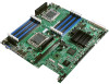
Intel® Server Boards S5520HC, S5500HCV and S5520HCT TPS Appendix E: POST Code Diagnostic LED Decoder Appendix E: POST Code Diagnostic LED Decoder During the system boot process, the BIOS executes a number of platform configuration processes, each of which is assigned a specific hex POST code number. As each configuration routine is started, the BIOS displays the POST code to the POST Code Diagnostic LEDs on the back edge of the server board. To assist in troubleshooting a system hang during the POST process, you can use the Diagnostic LEDs to identify the last POST process executed. Each POST code is represented by eight amber Diagnostic LEDs. The POST codes are divided into two nibbles: an upper nibble and a lower nibble. The upper nibble bits are represented by Diagnostic LED's #4, #5, #6, and #7. The lower nibble bits are represented by Diagnostics LED's #0, #1, #2, and #3. If the bit is set in the upper and lower nibbles, the corresponding LED lights up. If the bit is clear, the corresponding LED is off. Diagnostic LED #7 is labeled "MSB" (Most Significant Bit), and Diagnostic LED #0 is labeled "LSB" (Least Significant Bit). A. Diagnostic LED #7 (MSB LED) B. Diagnostic LED #6 C. Diagnostic LED #5 D. Diagnostic LED #4 E. Diagnostic LED #3 F. Diagnostic LED #2 G. Diagnostic LED #1 H. Diagnostic LED #0 (LSB LED) Figure 63. Diagnostic LED Placement Diagram In the following example, the BIOS sends a value of EDh to the diagnostic LED decoder. The LED's are decoded as follows: Table 84. POST Progress Code LED Example LED's Status Results Upper Nibble LED's Lower Nibble LED's LED LED LED LED LED LED LED LED #7 #6 #5 #4 #3 #2 #1 #0 8h 4h 2h 1h 8h 4h 2h 1h ON ON ON ON ON ON OFF ON 1 1 1 0 1 1 0 1 Eh Dh Revision 1.8 161 Intel order number E39529-013
-
 1
1 -
2
-
3
-
4
-
5
-
6
-
7
-
8
-
9
-
10
-
11
-
12
-
13
-
14
-
15
-
16
-
17
-
18
-
19
-
20
-
21
-
22
-
23
-
24
-
25
-
26
-
27
-
28
-
29
-
30
-
31
-
32
-
33
-
34
-
35
-
36
-
37
-
38
-
39
-
40
-
41
-
42
-
43
-
44
-
45
-
46
-
47
-
48
-
49
-
50
-
51
-
52
-
53
-
54
-
55
-
56
-
57
-
58
-
59
-
60
-
61
-
62
-
63
-
64
-
65
-
66
-
67
-
68
-
69
-
70
-
71
-
72
-
73
-
74
-
75
-
76
-
77
-
78
-
79
-
80
-
81
-
82
-
83
-
84
-
85
-
86
-
87
-
88
-
89
-
90
-
91
-
92
-
93
-
94
-
95
-
96
-
97
-
98
-
99
-
100
-
101
-
102
-
103
-
104
-
105
-
106
-
107
-
108
-
109
-
110
-
111
-
112
-
113
-
114
-
115
-
116
-
117
-
118
-
119
-
120
-
121
-
122
-
123
-
124
-
125
-
126
-
127
-
128
-
129
-
130
-
131
-
132
-
133
-
134
-
135
-
136
-
137
-
138
-
139
-
140
-
141
-
142
-
143
-
144
-
145
-
146
-
147
-
148
-
149
-
150
-
151
-
152
-
153
-
154
-
155
-
156
-
157
-
158
-
159
-
160
-
161
-
162
-
163
-
164
-
165
-
166
-
167
-
168
-
169
-
 170
170 -
 171
171 -
 172
172 -
 173
173 -
 174
174 -
 175
175 -
 176
176 -
 177
177 -
 178
178 -
 179
179 -
 180
180 -
181
-
182
-
183
-
184
-
185
-
186
-
187
-
188
-
189
-
190
 |
 |
