Intel BB5520UR Product Specification - Page 127
NIC Connectors, SATA Connectors, SAS Module Slot
 |
View all Intel BB5520UR manuals
Add to My Manuals
Save this manual to your list of manuals |
Page 127 highlights
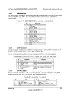
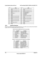
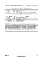
Intel® Server Boards S5520HC, S5500HCV, and S5520HCT TPS Connector/Header Locations and Pin-outs 6.5.2 NIC Connectors The server boards provide two stacked RJ-45/2xUSB connectors side-by-side on the back edge of the board (J5A1, J6A1). The pin-out for NIC connectors is identical and defined in the following table. Table 57. RJ-45 10/100/1000 NIC Connector Pin-out (J5A1, J6A1) Pin Signal Name 1 GND 2 P1V8_NIC 3 NIC_A_MDI3P 4 NIC_A_MDI3N 5 NIC_A_MDI2P 6 NIC_A_MDI2N 7 NIC_A_MDI1P 8 NIC_A_MDI1N 9 NIC_A_MDI0P 10 NIC_A_MDI0N 11 NIC_LINKA_1000_N (LED 12 NIC_LINKA_100_N (LED) 13 NIC_ACT_LED_N 14 NIC_LINK_LED_N 15 GND 16 GND 6.5.3 SATA Connectors The server boards provide up to six SATA connectors: SATA-0 (J1G5), SATA-1 (J1G4), SATA2 (J1G1), SATA-3 (J1F4), SATA-4 (J1F1), and SATA-5 (J1E3). The pin configuration for each connector is identical and defined in the following table: Table 58. SATA/SAS Connector Pin-out (J1E3, J1G1, J1G4, J1G5, J1F1, J1F4) Pin Signal Name 1 GND 2 SATA TX_P_C 3 SATA TX_N_C 4 GND 5 SATA _RX_N_C 6 SATA _RX_P_C 7 GND Description Ground Positive side of transmit differential pair Negative side of transmit differential pair Ground Negative side of receive differential pair Positive side of receive differential pair Ground 6.5.4 SAS Module Slot The server boards provide one SAS module slot (J2J1) to support the Intel® SAS Entry RAID Module AXX4SASMOD card. The following table defines the pin-out: Table 59. SAS Module Slot Pin-out (J2J1) Pin Name 1 P3V3_AUX 3 SW_RAID_MODE 5 PE_ICH10_SAS_SW_C_TP0 7 GND Pin Name 2 RST_LPC_SAS_N 4 GND 6 PE_ICH10_SAS_SW_C_TN0 8 GND Revision 1.8 113 Intel order number E39529-013
-
 1
1 -
2
-
3
-
4
-
5
-
6
-
7
-
8
-
9
-
10
-
11
-
12
-
13
-
14
-
15
-
16
-
17
-
18
-
19
-
20
-
21
-
22
-
23
-
24
-
25
-
26
-
27
-
28
-
29
-
30
-
31
-
32
-
33
-
34
-
35
-
36
-
37
-
38
-
39
-
40
-
41
-
42
-
43
-
44
-
45
-
46
-
47
-
48
-
49
-
50
-
51
-
52
-
53
-
54
-
55
-
56
-
57
-
58
-
59
-
60
-
61
-
62
-
63
-
64
-
65
-
66
-
67
-
68
-
69
-
70
-
71
-
72
-
73
-
74
-
75
-
76
-
77
-
78
-
79
-
80
-
81
-
82
-
83
-
84
-
85
-
86
-
87
-
88
-
89
-
90
-
91
-
92
-
93
-
94
-
95
-
96
-
97
-
98
-
99
-
100
-
101
-
102
-
103
-
104
-
105
-
106
-
107
-
108
-
109
-
110
-
111
-
112
-
113
-
114
-
115
-
116
-
117
-
118
-
119
-
120
-
121
-
 122
122 -
 123
123 -
 124
124 -
 125
125 -
 126
126 -
 127
127 -
 128
128 -
 129
129 -
 130
130 -
 131
131 -
 132
132 -
133
-
134
-
135
-
136
-
137
-
138
-
139
-
140
-
141
-
142
-
143
-
144
-
145
-
146
-
147
-
148
-
149
-
150
-
151
-
152
-
153
-
154
-
155
-
156
-
157
-
158
-
159
-
160
-
161
-
162
-
163
-
164
-
165
-
166
-
167
-
168
-
169
-
170
-
171
-
172
-
173
-
174
-
175
-
176
-
177
-
178
-
179
-
180
-
181
-
182
-
183
-
184
-
185
-
186
-
187
-
188
-
189
-
190
 |
 |
