Intel BB5520UR Product Specification - Page 6
Connector/Header Locations and Pin-outs, Jumper Blocks, Intel, Light Guided Diagnostics, Design
 |
View all Intel BB5520UR manuals
Add to My Manuals
Save this manual to your list of manuals |
Page 6 highlights
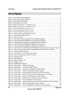
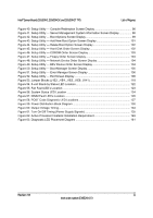
Table of Contents Intel® Server Boards S5520HC, S5500HCV, and S5520HCT TPS 5.3 BIOS Setup Utility...72 5.3.1 Operation ...72 5.3.2 Server Platform Setup Utility Screens 75 6. Connector/Header Locations and Pin-outs 108 6.1 Board Connector Information 108 6.2 Power Connectors 109 6.3 System Management Headers 110 6.3.1 Intel® Remote Management Module 3 Connector 110 6.3.2 LCP/IPMB Header 111 6.3.3 HSBP Header ...111 6.3.4 SGPIO Header ...111 6.4 Front Panel Connector 111 6.5 I/O Connectors ...112 6.5.1 VGA Connector ...112 6.5.2 NIC Connectors ...113 6.5.3 SATA Connectors 113 6.5.4 SAS Module Slot 113 6.5.5 Serial Port Connectors 114 6.5.6 USB Connector ...115 6.6 Fan Headers...116 7. Jumper Blocks...118 7.1 CMOS Clear and Password Reset Usage Procedure 119 7.1.1 Clearing the CMOS 119 7.1.2 Clearing the Password 119 7.2 Force BMC Update Procedure 120 7.3 BIOS Recovery Jumper 120 8. Intel® Light Guided Diagnostics 122 8.1 5-volt Stand-by LED 122 8.2 Fan Fault LED's...123 8.3 System ID LED and System Status LED 124 8.4 DIMM Fault LEDs 126 8.5 Post Code Diagnostic LEDs 127 9. Design and Environmental Specifications 128 9.1 Intel® Server Boards S5520HC, S5500HCV, and S5520HCT Design Specifications128 9.2 MTBF ...128 9.3 Server Board Power Requirements 130 9.3.1 Processor Power Support 131 9.4 Power Supply Output Requirements 131 9.4.1 Grounding...131 9.4.2 Stand-by Outputs 131 9.4.3 Remote Sense...132 vi Revision 1.8 Intel order number E39529-013
-
 1
1 -
 2
2 -
 3
3 -
 4
4 -
 5
5 -
 6
6 -
 7
7 -
 8
8 -
 9
9 -
 10
10 -
 11
11 -
 12
12 -
13
-
14
-
15
-
16
-
17
-
18
-
19
-
20
-
21
-
22
-
23
-
24
-
25
-
26
-
27
-
28
-
29
-
30
-
31
-
32
-
33
-
34
-
35
-
36
-
37
-
38
-
39
-
40
-
41
-
42
-
43
-
44
-
45
-
46
-
47
-
48
-
49
-
50
-
51
-
52
-
53
-
54
-
55
-
56
-
57
-
58
-
59
-
60
-
61
-
62
-
63
-
64
-
65
-
66
-
67
-
68
-
69
-
70
-
71
-
72
-
73
-
74
-
75
-
76
-
77
-
78
-
79
-
80
-
81
-
82
-
83
-
84
-
85
-
86
-
87
-
88
-
89
-
90
-
91
-
92
-
93
-
94
-
95
-
96
-
97
-
98
-
99
-
100
-
101
-
102
-
103
-
104
-
105
-
106
-
107
-
108
-
109
-
110
-
111
-
112
-
113
-
114
-
115
-
116
-
117
-
118
-
119
-
120
-
121
-
122
-
123
-
124
-
125
-
126
-
127
-
128
-
129
-
130
-
131
-
132
-
133
-
134
-
135
-
136
-
137
-
138
-
139
-
140
-
141
-
142
-
143
-
144
-
145
-
146
-
147
-
148
-
149
-
150
-
151
-
152
-
153
-
154
-
155
-
156
-
157
-
158
-
159
-
160
-
161
-
162
-
163
-
164
-
165
-
166
-
167
-
168
-
169
-
170
-
171
-
172
-
173
-
174
-
175
-
176
-
177
-
178
-
179
-
180
-
181
-
182
-
183
-
184
-
185
-
186
-
187
-
188
-
189
-
190
 |
 |
