Intel BB5520UR Product Specification - Page 57
Table 9. Intel, Server Board S5500HCV PCI Bus Segment Characteristics, Table 10. Intel, Server Board
 |
View all Intel BB5520UR manuals
Add to My Manuals
Save this manual to your list of manuals |
Page 57 highlights
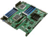
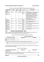
Intel® Server Boards S5520HC, S5500HCV, and S5520HCT TPS Functional Architecture Table 9. Intel® Server Board S5500HCV PCI Bus Segment Characteristics PCI Bus Segment PCI32 ICH10R PE1, PE2, PE3, PE4 ICH10R PCI Express* Ports Voltage 5 V 3.3 V PE5 ICH10R PCI Express* Port PE1, PE2 5500 IOH PCI Express* Ports PE3 5500 IOH PCI Express* Port PE7, PE8 5500 IOH PCI Express* Ports PE9, PE10 5500 IOH PCI Express* Ports 3.3 V 3.3 V 3.3 V 3.3 V 3.3 V Width Speed 32 bit 33 MHz Type PCI PCI I/O Card Slots PCI Slot 1 x4 10 Gb/s PCI x4 PCI Express* Gen1 throughput to Slot Express* 2 and Intel® SAS Entry RAID Module Gen1 AXX4SASMOD slot (x8 mechanically) (Default to Slot 2, and switch to SAS Module slot when Intel® SAS Entry RAID Module AXX4SASMOD is detected). This PCI Express* Gen1 slot is not available when the SAS module slot is in use and vice versa. x1 2.5 Gb/s PCI x1 PCI Express* Gen1 throughput to Express* onboard Integrated BMC Gen1 x4 10 Gb/s PCI x4 PCI Express* Gen2 throughput to Express* onboard NIC (82575EB) Gen1 x4 10 Gb/S PCI x4 PCI Express* Gen1 throughput to Slot Express* 6 (x16 mechanically) Gen2 x8 40 Gb/S PCI x8 PCI Express* Gen2 throughput to Slot Express* 4 (x8 mechanically) Gen2 x8 40 Gb/S PCI x8 PCI Express* Gen2 throughput to Slot Express* 3 (x8 mechanically) Gen2 3.5.1 PCI Express* Riser Slot (S5520HC - Slot 6) One PCI Express* pin is designated as Riser Card Type pin with the definitions noted in the following table for Intel® Server Board S5520HC PCI Express* slot 6. Table 10. Intel® Server Board S5520HC PCI Riser Slot (Slot 6) PCI Express* Gen2 Slot 6 Setup1 IOH PEWIDTH [2] PCI Riser Strap PCI Express* Pin A50 [RVSD] Type 1 Riser, One x8 PCI Express* Slot2 1 Type 2 Riser, Two x4 PCI Express* Slot3 0 1. Maximum power rating of Slot 6 for riser is 75 W, provided no card is in slots 3, 4, and 5. 2. The type 1 riser card must follow the standard PCI Express* Adapter pin-out and leave pin A50 as a No-Connect (NC). 3. The type 2 riser card must connect the PCI Express* pin A50 with a 4.7K ohm resistor to pull up to 3.3 V. The following table provides the supported bus throughput for the given riser card used and the number of add-in cards installed. Table 11. PCI Riser Support PCI Express* Gen2 Slot 6 Riser Support One Add-in card Two Add-in cards Type 1 Riser Card x8 N/A Type 2 Riser Card x4 x4 There are no population rules for installing a single add-in card in the Type 2 riser card; you can install a single add-in card in either PCI Express* slot. Revision 1.8 43 Intel order number E39529-013
-
 1
1 -
2
-
3
-
4
-
5
-
6
-
7
-
8
-
9
-
10
-
11
-
12
-
13
-
14
-
15
-
16
-
17
-
18
-
19
-
20
-
21
-
22
-
23
-
24
-
25
-
26
-
27
-
28
-
29
-
30
-
31
-
32
-
33
-
34
-
35
-
36
-
37
-
38
-
39
-
40
-
41
-
42
-
43
-
44
-
45
-
46
-
47
-
48
-
49
-
50
-
51
-
 52
52 -
 53
53 -
 54
54 -
 55
55 -
 56
56 -
 57
57 -
 58
58 -
 59
59 -
 60
60 -
 61
61 -
 62
62 -
63
-
64
-
65
-
66
-
67
-
68
-
69
-
70
-
71
-
72
-
73
-
74
-
75
-
76
-
77
-
78
-
79
-
80
-
81
-
82
-
83
-
84
-
85
-
86
-
87
-
88
-
89
-
90
-
91
-
92
-
93
-
94
-
95
-
96
-
97
-
98
-
99
-
100
-
101
-
102
-
103
-
104
-
105
-
106
-
107
-
108
-
109
-
110
-
111
-
112
-
113
-
114
-
115
-
116
-
117
-
118
-
119
-
120
-
121
-
122
-
123
-
124
-
125
-
126
-
127
-
128
-
129
-
130
-
131
-
132
-
133
-
134
-
135
-
136
-
137
-
138
-
139
-
140
-
141
-
142
-
143
-
144
-
145
-
146
-
147
-
148
-
149
-
150
-
151
-
152
-
153
-
154
-
155
-
156
-
157
-
158
-
159
-
160
-
161
-
162
-
163
-
164
-
165
-
166
-
167
-
168
-
169
-
170
-
171
-
172
-
173
-
174
-
175
-
176
-
177
-
178
-
179
-
180
-
181
-
182
-
183
-
184
-
185
-
186
-
187
-
188
-
189
-
190
 |
 |