Intel BB5520UR Product Specification - Page 8

List of s

Page 8 highlights

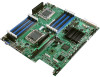
List of Figures Intel® Server Boards S5520HC, S5500HCV, and S5520HCT TPS List of Figures Figure 1. Intel® Server Board S5520HC 5 Figure 2. Intel® Server Board S5500HCV 5 Figure 3. Major Board Components 7 Figure 4. Mounting Hole Locations 8 Figure 5. Major Connector Pin-1 Locations (1 of 2 9 Figure 6. Major Connector Pin-1 Locations (2 of 2 10 Figure 7. Primary Side Keep-out Zone (1 of 2 11 Figure 8. Primary Side Keep-out Zone (2 of 2 12 Figure 9. Primary Side Air Duct Keep-out Zone 13 Figure 10. Primary Side Card-Side Keep-out Zone 14 Figure 11. Second Side Keep-out Zone 15 Figure 12. Rear I/O Layout ...16 Figure 13. Intel® Server Board S5520HC Functional Block Diagram 18 Figure 14. Intel® Server Board S5500HCV Functional Block Diagram 19 Figure 15. Unified Retention System and Unified Back Plate Assembly 26 Figure 16. Intel® Server Board S5520HC DIMM Slots Arrangement 28 Figure 17. Intel® Server Board S5500HCV DIMM Slots Arrangement 29 Figure 18. Intel® SAS Entry RAID Module AXX4SASMOD Component and Connector Layout 44 Figure 19. Intel® SAS Entry RAID Module AXX4SASMOD Functional Block Diagram 45 Figure 20. Integrated BMC Hardware 48 Figure 21. Setup Utility - TPM Configuration Screen 54 Figure 22. Setting Administrator password in BIOS 56 Figure 23. Activating TPM ...57 Figure 24. TPM activated...58 Figure 25. BIOS setting for TXT 59 Figure 26. Platform Control ...67 Figure 27. SMBUS Block Diagram 71 Figure 28. Setup Utility - Main Screen Display 76 Figure 29. Setup Utility - Advanced Screen Display 78 Figure 30. Setup Utility - Processor Configuration Screen Display 79 Figure 31. Setup Utility - Memory Configuration Screen Display 82 Figure 32. Setup Utility - Configure RAS and Performance Screen Display 84 Figure 33. Setup Utility - Mass Storage Controller Configuration Screen Display 85 Figure 34. Setup Utility - Serial Port Configuration Screen Display 87 Figure 35. Setup Utility - USB Controller Configuration Screen Display 88 Figure 36. Setup Utility - PCI Configuration Screen Display 90 Figure 37. Setup Utility - System Acoustic and Performance Configuration Screen Display ... 91 Figure 38. Setup Utility - Security Configuration Screen Display 92 Figure 39. Setup Utility - Server Management Configuration Screen Display 95 viii Revision 1.8 Intel order number E39529-013

  • 1
  • 2
  • 3
  • 4
  • 5
  • 6
  • 7
  • 8
  • 9
  • 10
  • 11
  • 12
  • 13
  • 14
  • 15
  • 16
  • 17
  • 18
  • 19
  • 20
  • 21
  • 22
  • 23
  • 24
  • 25
  • 26
  • 27
  • 28
  • 29
  • 30
  • 31
  • 32
  • 33
  • 34
  • 35
  • 36
  • 37
  • 38
  • 39
  • 40
  • 41
  • 42
  • 43
  • 44
  • 45
  • 46
  • 47
  • 48
  • 49
  • 50
  • 51
  • 52
  • 53
  • 54
  • 55
  • 56
  • 57
  • 58
  • 59
  • 60
  • 61
  • 62
  • 63
  • 64
  • 65
  • 66
  • 67
  • 68
  • 69
  • 70
  • 71
  • 72
  • 73
  • 74
  • 75
  • 76
  • 77
  • 78
  • 79
  • 80
  • 81
  • 82
  • 83
  • 84
  • 85
  • 86
  • 87
  • 88
  • 89
  • 90
  • 91
  • 92
  • 93
  • 94
  • 95
  • 96
  • 97
  • 98
  • 99
  • 100
  • 101
  • 102
  • 103
  • 104
  • 105
  • 106
  • 107
  • 108
  • 109
  • 110
  • 111
  • 112
  • 113
  • 114
  • 115
  • 116
  • 117
  • 118
  • 119
  • 120
  • 121
  • 122
  • 123
  • 124
  • 125
  • 126
  • 127
  • 128
  • 129
  • 130
  • 131
  • 132
  • 133
  • 134
  • 135
  • 136
  • 137
  • 138
  • 139
  • 140
  • 141
  • 142
  • 143
  • 144
  • 145
  • 146
  • 147
  • 148
  • 149
  • 150
  • 151
  • 152
  • 153
  • 154
  • 155
  • 156
  • 157
  • 158
  • 159
  • 160
  • 161
  • 162
  • 163
  • 164
  • 165
  • 166
  • 167
  • 168
  • 169
  • 170
  • 171
  • 172
  • 173
  • 174
  • 175
  • 176
  • 177
  • 178
  • 179
  • 180
  • 181
  • 182
  • 183
  • 184
  • 185
  • 186
  • 187
  • 188
  • 189
  • 190

List of Figures
Intel® Server Boards S5520HC, S5500HCV, and S5520HCT TPS
Revision 1.8
Intel order number E39529-013
viii
List of Figures
Figure 1. Intel
®
Server Board S5520HC
.........................................................................................
5
Figure 2. Intel
®
Server Board S5500HCV
......................................................................................
5
Figure 3. Major Board Components
...............................................................................................
7
Figure 4. Mounting Hole Locations
.................................................................................................
8
Figure 5. Major Connector Pin-1 Locations (1 of 2)
.......................................................................
9
Figure 6. Major Connector Pin-1 Locations (2 of 2)
.....................................................................
10
Figure 7. Primary Side Keep-out Zone (1 of 2)
............................................................................
11
Figure 8. Primary Side Keep-out Zone (2 of 2)
............................................................................
12
Figure 9. Primary Side Air Duct Keep-out Zone
...........................................................................
13
Figure 10. Primary Side Card-Side Keep-out Zone
.....................................................................
14
Figure 11. Second Side Keep-out Zone
.......................................................................................
15
Figure 12. Rear I/O Layout
...........................................................................................................
16
Figure 13. Intel
®
Server Board S5520HC Functional Block Diagram
..........................................
18
Figure 14. Intel
®
Server Board S5500HCV Functional Block Diagram
........................................
19
Figure 15. Unified Retention System and Unified Back Plate Assembly
.....................................
26
Figure 16. Intel
®
Server Board S5520HC DIMM Slots Arrangement
...........................................
28
Figure 17. Intel
®
Server Board S5500HCV DIMM Slots Arrangement
........................................
29
Figure 18. Intel
®
SAS Entry RAID Module AXX4SASMOD Component and Connector Layout 44
Figure 19. Intel
®
SAS Entry RAID Module AXX4SASMOD Functional Block Diagram
...............
45
Figure 20. Integrated BMC Hardware
..........................................................................................
48
Figure 21. Setup Utility – TPM Configuration Screen
..................................................................
54
Figure 22. Setting Administrator password in BIOS
.....................................................................
56
Figure 23. Activating TPM
............................................................................................................
57
Figure 24. TPM activated
..............................................................................................................
58
Figure 25. BIOS setting for TXT
...................................................................................................
59
Figure 26. Platform Control
..........................................................................................................
67
Figure 27. SMBUS Block Diagram
...............................................................................................
71
Figure 28. Setup Utility — Main Screen Display
..........................................................................
76
Figure 29. Setup Utility — Advanced Screen Display
..................................................................
78
Figure 30. Setup Utility — Processor Configuration Screen Display
...........................................
79
Figure 31. Setup Utility — Memory Configuration Screen Display
..............................................
82
Figure 32. Setup Utility — Configure RAS and Performance Screen Display
............................
84
Figure 33. Setup Utility — Mass Storage Controller Configuration Screen Display
....................
85
Figure 34. Setup Utility — Serial Port Configuration Screen Display
..........................................
87
Figure 35. Setup Utility — USB Controller Configuration Screen Display
...................................
88
Figure 36. Setup Utility — PCI Configuration Screen Display
.....................................................
90
Figure 37. Setup Utility — System Acoustic and Performance Configuration Screen Display ... 91
Figure 38. Setup Utility — Security Configuration Screen Display
..............................................
92
Figure 39. Setup Utility — Server Management Configuration Screen Display
..........................
95