Intel BB5520UR Product Specification - Page 134
Force BMC Update Procedure, BIOS Recovery Jumper
 |
View all Intel BB5520UR manuals
Add to My Manuals
Save this manual to your list of manuals |
Page 134 highlights
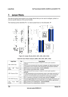
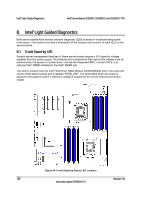
Jumper Blocks Intel® Server Boards S5520HC, S5500HCV, and S5520HCT TPS 7.2 Force BMC Update Procedure When performing a standard BMC firmware update procedure, the update utility places the BMC into an update mode, allowing the firmware to load safely onto the flash device. In the unlikely event the BMC firmware update process fails due to the BMC not being in the proper update state, the server boards provide a Force BMC Update jumper (J1H1) that forces the BMC into the proper update state. In the event the standard BMC firmware update process fails, complete the following procedure: 1. Power down and remove the AC power cord. 2. Open the server chassis. See your server chassis documentation for instructions. 3. Move the jumper (J1H1) from the default operating position (covering pins 1 and 2) to the enabled position (covering pins 2 and 3). 4. Close the server chassis. 5. Reconnect the AC power cord and power up the server. 6. Perform the BMC firmware update procedure as documented in the Update_Instruction.txt file included in the given BMC firmware update package. After successful completion of the firmware update process, the firmware update utility may generate an error stating the BMC is still in update mode. 7. Power down and remove the AC power cord. 8. Open the server chassis. 9. Move the jumper (J1H1) from the enabled position (covering pins 2 and 3) to the disabled position (covering pins 1 and 2). 10. Close the server chassis. 11. Reconnect the AC power cord and power up the server. Note: When the Force BMC Update jumper is set to the enabled position, normal BMC functionality is disabled. You should never run the server with the Force BMC Update jumper set in this position. You should only use this jumper setting when the standard firmware update process fails. When the server is running normally, this jumper must remain in the default/disabled position. 7.3 BIOS Recovery Jumper 1. Power down the system and remove the AC power cord. 2. Open the server chassis. See your server chassis documentation for instructions. 3. Move the BIOS recovery jumper (J1E5) from the default operating position (covering pins 1 and 2) to the enabled position (covering pins 2 and 3). 4. Close the server chassis. 5. Reconnect the AC power cord and power up the server. 6. Perform the BIOS Recovery procedure as documented in the BIOS release notes. 7. After successful completion of the BIOS recovery, the "BIOS has been updated successfully" message displays. 120 Revision 1.8 Intel order number E39529-013
-
 1
1 -
2
-
3
-
4
-
5
-
6
-
7
-
8
-
9
-
10
-
11
-
12
-
13
-
14
-
15
-
16
-
17
-
18
-
19
-
20
-
21
-
22
-
23
-
24
-
25
-
26
-
27
-
28
-
29
-
30
-
31
-
32
-
33
-
34
-
35
-
36
-
37
-
38
-
39
-
40
-
41
-
42
-
43
-
44
-
45
-
46
-
47
-
48
-
49
-
50
-
51
-
52
-
53
-
54
-
55
-
56
-
57
-
58
-
59
-
60
-
61
-
62
-
63
-
64
-
65
-
66
-
67
-
68
-
69
-
70
-
71
-
72
-
73
-
74
-
75
-
76
-
77
-
78
-
79
-
80
-
81
-
82
-
83
-
84
-
85
-
86
-
87
-
88
-
89
-
90
-
91
-
92
-
93
-
94
-
95
-
96
-
97
-
98
-
99
-
100
-
101
-
102
-
103
-
104
-
105
-
106
-
107
-
108
-
109
-
110
-
111
-
112
-
113
-
114
-
115
-
116
-
117
-
118
-
119
-
120
-
121
-
122
-
123
-
124
-
125
-
126
-
127
-
128
-
 129
129 -
 130
130 -
 131
131 -
 132
132 -
 133
133 -
 134
134 -
 135
135 -
 136
136 -
 137
137 -
 138
138 -
 139
139 -
140
-
141
-
142
-
143
-
144
-
145
-
146
-
147
-
148
-
149
-
150
-
151
-
152
-
153
-
154
-
155
-
156
-
157
-
158
-
159
-
160
-
161
-
162
-
163
-
164
-
165
-
166
-
167
-
168
-
169
-
170
-
171
-
172
-
173
-
174
-
175
-
176
-
177
-
178
-
179
-
180
-
181
-
182
-
183
-
184
-
185
-
186
-
187
-
188
-
189
-
190
 |
 |
