Lexmark X264 Service Manual - Page 116
Printhead assembly mechanical adjustment, Diagnostics Menu Diag Menu
 |
View all Lexmark X264 manuals
Add to My Manuals
Save this manual to your list of manuals |
Page 116 highlights
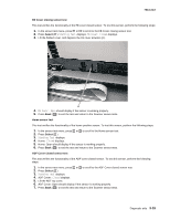
7013-XXX 7. Print the Quick Test page again, and check that the darkest line in the center graph is equal to zero. If it is, then check to see if the left, top, and bottom margins are detected. If it is not, then repeat step 5. Note: The alignment of the left margin positions the plane to the right or left. The alignment of the right margin does not alter the margins and should only be used to adjust the printhead. Printhead assembly mechanical adjustment A printhead needs to be correctly positioned after it has been removed. Use a pencil to mark the screw locations of the old printhead on the metal frame. Align the new printhead relative to the location of the old printhead. Note: Skew is caused by a sheet being fed through the printer while misaligned. The entire image is rotated relative to the sheet edges. However, a mechanically misaligned printhead causes the horizontal lines to appear skewed while the vertical lines remain parallel to the vertical edges.There are no adjustments for skew. Check the pick roll (paper pick assembly) for wear, the paper path for obstructions, the fuser for proper setting, and the tray paper guides for fit to the media. Paper feed skew Printhead misalignment To adjust the printhead: 1. Enter the Diagnostics Menu. See "Diagnostics Menu (Diag Menu)" on page 3-2. 2. Select PRINT TESTS. 3. Select Tray 1. 4. Select Single. 5. Fold the printed test page on the left side so that a few millimeters of grid lines wrap around the outside of the fold. See image below. 6. Fold a second vertical fold near the center so that the left side top edge aligns with the right side top edge. 3-24 Service Manual
-
 1
1 -
2
-
3
-
4
-
5
-
6
-
7
-
8
-
9
-
10
-
11
-
12
-
13
-
14
-
15
-
16
-
17
-
18
-
19
-
20
-
21
-
22
-
23
-
24
-
25
-
26
-
27
-
28
-
29
-
30
-
31
-
32
-
33
-
34
-
35
-
36
-
37
-
38
-
39
-
40
-
41
-
42
-
43
-
44
-
45
-
46
-
47
-
48
-
49
-
50
-
51
-
52
-
53
-
54
-
55
-
56
-
57
-
58
-
59
-
60
-
61
-
62
-
63
-
64
-
65
-
66
-
67
-
68
-
69
-
70
-
71
-
72
-
73
-
74
-
75
-
76
-
77
-
78
-
79
-
80
-
81
-
82
-
83
-
84
-
85
-
86
-
87
-
88
-
89
-
90
-
91
-
92
-
93
-
94
-
95
-
96
-
97
-
98
-
99
-
100
-
101
-
102
-
103
-
104
-
105
-
106
-
107
-
108
-
109
-
110
-
 111
111 -
 112
112 -
 113
113 -
 114
114 -
 115
115 -
 116
116 -
 117
117 -
 118
118 -
 119
119 -
 120
120 -
 121
121 -
122
-
123
-
124
-
125
-
126
-
127
-
128
-
129
-
130
-
131
-
132
-
133
-
134
-
135
-
136
-
137
-
138
-
139
-
140
-
141
-
142
-
143
-
144
-
145
-
146
-
147
-
148
-
149
-
150
-
151
-
152
-
153
-
154
-
155
-
156
-
157
-
158
-
159
-
160
-
161
-
162
-
163
-
164
-
165
-
166
-
167
-
168
-
169
-
170
-
171
-
172
-
173
-
174
-
175
-
176
-
177
-
178
-
179
-
180
-
181
-
182
-
183
-
184
-
185
-
186
-
187
-
188
-
189
-
190
-
191
-
192
-
193
-
194
-
195
-
196
-
197
-
198
-
199
-
200
-
201
-
202
-
203
-
204
-
205
-
206
-
207
-
208
-
209
-
210
-
211
-
212
-
213
-
214
-
215
-
216
-
217
-
218
-
219
-
220
-
221
-
222
-
223
-
224
-
225
-
226
-
227
-
228
-
229
-
230
-
231
-
232
-
233
-
234
-
235
-
236
-
237
-
238
-
239
-
240
-
241
-
242
-
243
-
244
-
245
-
246
-
247
-
248
-
249
-
250
 |
 |
