Lexmark X264 Service Manual - Page 86
Modem / fax card service check, 3.3VDC. Pin 7 for +5VDC. 9
 |
View all Lexmark X264 manuals
Add to My Manuals
Save this manual to your list of manuals |
Page 86 highlights
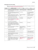
7013-XXX Modem / fax card service check Step 1 2 3 4 5 6 7 8 Questions / actions Yes Is the phone line properly connected to the modem card and the wall jack? Go to step 3. Properly connect the phone line to the modem card and wall jack. Problem resolved. Did this fix the problem? Test the phone line's ability to send and receive calls. Go to step 5. Did the phone line work properly? Use the MFP on a properly functioning phone jack. Did this fix the problem? Problem resolved. Is the modem card ribbon cable properly connected to the controller board at JMOD2 and the modem card? Go to step 7. Properly connect the modem card cable to the modem card and controller board. Did this fix the problem? Problem resolved. Check the modem card ribbon cable for continuity. Is there continuity? Go to step 8. Check the voltages from connector J39 on the controller board. Check Pin 4 and 5 for +3.3VDC. Pin 7 for +5VDC. 9, 11, 13, 15, 17, and 19 are grounds. Are the signals or voltages present? Replace the modem card. No Go to step 2. Go to step 3. Go to step 4. Go to step 5. Go to step 6. Go to step 7. Replace the modem card cable. Replace the controller board. See "Controller board removal" on page 4-13. 2-52 Service Manual
-
 1
1 -
2
-
3
-
4
-
5
-
6
-
7
-
8
-
9
-
10
-
11
-
12
-
13
-
14
-
15
-
16
-
17
-
18
-
19
-
20
-
21
-
22
-
23
-
24
-
25
-
26
-
27
-
28
-
29
-
30
-
31
-
32
-
33
-
34
-
35
-
36
-
37
-
38
-
39
-
40
-
41
-
42
-
43
-
44
-
45
-
46
-
47
-
48
-
49
-
50
-
51
-
52
-
53
-
54
-
55
-
56
-
57
-
58
-
59
-
60
-
61
-
62
-
63
-
64
-
65
-
66
-
67
-
68
-
69
-
70
-
71
-
72
-
73
-
74
-
75
-
76
-
77
-
78
-
79
-
80
-
 81
81 -
 82
82 -
 83
83 -
 84
84 -
 85
85 -
 86
86 -
 87
87 -
 88
88 -
 89
89 -
 90
90 -
 91
91 -
92
-
93
-
94
-
95
-
96
-
97
-
98
-
99
-
100
-
101
-
102
-
103
-
104
-
105
-
106
-
107
-
108
-
109
-
110
-
111
-
112
-
113
-
114
-
115
-
116
-
117
-
118
-
119
-
120
-
121
-
122
-
123
-
124
-
125
-
126
-
127
-
128
-
129
-
130
-
131
-
132
-
133
-
134
-
135
-
136
-
137
-
138
-
139
-
140
-
141
-
142
-
143
-
144
-
145
-
146
-
147
-
148
-
149
-
150
-
151
-
152
-
153
-
154
-
155
-
156
-
157
-
158
-
159
-
160
-
161
-
162
-
163
-
164
-
165
-
166
-
167
-
168
-
169
-
170
-
171
-
172
-
173
-
174
-
175
-
176
-
177
-
178
-
179
-
180
-
181
-
182
-
183
-
184
-
185
-
186
-
187
-
188
-
189
-
190
-
191
-
192
-
193
-
194
-
195
-
196
-
197
-
198
-
199
-
200
-
201
-
202
-
203
-
204
-
205
-
206
-
207
-
208
-
209
-
210
-
211
-
212
-
213
-
214
-
215
-
216
-
217
-
218
-
219
-
220
-
221
-
222
-
223
-
224
-
225
-
226
-
227
-
228
-
229
-
230
-
231
-
232
-
233
-
234
-
235
-
236
-
237
-
238
-
239
-
240
-
241
-
242
-
243
-
244
-
245
-
246
-
247
-
248
-
249
-
250
 |
 |
