Lexmark X264 Service Manual - Page 64
Main motor service check, Media feed clutch service check, Does this solve the problem?
 |
View all Lexmark X264 manuals
Add to My Manuals
Save this manual to your list of manuals |
Page 64 highlights
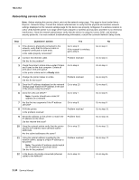
7013-XXX Main motor service check FRU Main motor gear drive Main motor cable LVPS/HVPS Controller board Warning: Do not replace the operator panel and controller board at the same time. Each card contains the printer settings. When either of these cards is new, it obtains the settings from the other card. Settings are lost when both are new and replaced at the same time. Action Turn off the printer, and unplug the main motor cable at J19. Turn on the printer, and check for the following voltages at J19: J19 pins Pins 1-4, 6 Pins 7-9 Voltages Approx. 5 V dc 18 V dc-24 V dc Verify ground at pin 5 for both the card and cable. • If these voltages are correct, then check the main motor cable for continuity. - Remove the left side cover to access the connector on the motor. - If continuity exists on each wire, then replace the main motor gear drive which includes the motor. - If continuity does not exist on one or more of the wires, then call the next level of support. • If these voltages are not correct, then see "Controller board connector pin values" on page 5-3, or replace the controller board. See "Controller board removal" on page 4-13. Media feed clutch service check Step 1 Action and questions Clear the paper path of all sheets of paper. Turn on the printer. Open the front door of the printer. Yes Go to step 3. No Go to step 2. Is the paper overlapping with no space between the trailing edge of the first sheet and leading edge of the second? 2 Check the paper path sensors for any dirt, Problem resolved dust or paper that might be obstructing the sensors. Does this solve the problem? 3 Replace the media feed clutch. See "Media feed clutch removal" on page 4-51. Does this solve the problem? Problem resolved 2-30 Service Manual Go to step 3. Contact your next level of support.
-
 1
1 -
2
-
3
-
4
-
5
-
6
-
7
-
8
-
9
-
10
-
11
-
12
-
13
-
14
-
15
-
16
-
17
-
18
-
19
-
20
-
21
-
22
-
23
-
24
-
25
-
26
-
27
-
28
-
29
-
30
-
31
-
32
-
33
-
34
-
35
-
36
-
37
-
38
-
39
-
40
-
41
-
42
-
43
-
44
-
45
-
46
-
47
-
48
-
49
-
50
-
51
-
52
-
53
-
54
-
55
-
56
-
57
-
58
-
 59
59 -
 60
60 -
 61
61 -
 62
62 -
 63
63 -
 64
64 -
 65
65 -
 66
66 -
 67
67 -
 68
68 -
 69
69 -
70
-
71
-
72
-
73
-
74
-
75
-
76
-
77
-
78
-
79
-
80
-
81
-
82
-
83
-
84
-
85
-
86
-
87
-
88
-
89
-
90
-
91
-
92
-
93
-
94
-
95
-
96
-
97
-
98
-
99
-
100
-
101
-
102
-
103
-
104
-
105
-
106
-
107
-
108
-
109
-
110
-
111
-
112
-
113
-
114
-
115
-
116
-
117
-
118
-
119
-
120
-
121
-
122
-
123
-
124
-
125
-
126
-
127
-
128
-
129
-
130
-
131
-
132
-
133
-
134
-
135
-
136
-
137
-
138
-
139
-
140
-
141
-
142
-
143
-
144
-
145
-
146
-
147
-
148
-
149
-
150
-
151
-
152
-
153
-
154
-
155
-
156
-
157
-
158
-
159
-
160
-
161
-
162
-
163
-
164
-
165
-
166
-
167
-
168
-
169
-
170
-
171
-
172
-
173
-
174
-
175
-
176
-
177
-
178
-
179
-
180
-
181
-
182
-
183
-
184
-
185
-
186
-
187
-
188
-
189
-
190
-
191
-
192
-
193
-
194
-
195
-
196
-
197
-
198
-
199
-
200
-
201
-
202
-
203
-
204
-
205
-
206
-
207
-
208
-
209
-
210
-
211
-
212
-
213
-
214
-
215
-
216
-
217
-
218
-
219
-
220
-
221
-
222
-
223
-
224
-
225
-
226
-
227
-
228
-
229
-
230
-
231
-
232
-
233
-
234
-
235
-
236
-
237
-
238
-
239
-
240
-
241
-
242
-
243
-
244
-
245
-
246
-
247
-
248
-
249
-
250
 |
 |
