Panasonic CS-E18SD3UAW service manual - Page 2

Table Of Contents

Page 2 highlights

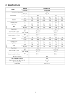
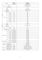
TABLE OF CONTENTS PAGE 1. Safety Precautions 3 2. Specifications 5 3. Features 14 4. Location of Controls and Components..........15 4.1 Indoor Unit 15 4.2 Outdoor Unit 15 4.3 Remote Control 15 5. Dimensions 16 5.1 Indoor Unit 16 5.2 Outdoor Unit 17 6. Refrigeration Cycle Diagram 18 6.1 CS-E9SD3UAW CU-E9SD3UA 18 6.2 CS-E12SD3UAW CU-E12SD3UA 19 6.3 CS-E18SD3UAW CU-E18SD3UA 20 7. Block Diagram 21 7.1 CS-E9SD3UAW CU-E9SD3UA CS-E12SD3UAW CU-E12SD3UA 21 7.2 CS-E18SD3UAW CU-E18SD3UA 22 8. Wiring Connection Diagram 23 8.1 Indoor Unit 23 8.2 Outdoor Unit 24 9. Electronic Circuit Diagram 26 9.1 Indoor Unit 26 9.2 Outdoor Unit 27 10. Printed Circuit Board 29 10.1 Indoor Unit 29 10.2 Outdoor Unit 30 11. Installation Instruction 33 11.1 Indoor Unit 35 11.2 Outdoor Unit 43 12. Operation and Control 48 12.1 Basic Function 48 12.2 Quiet Operation (Cooling Mode/Cooling Area of Soft Dry Mode 51 12.3 Powerful Mode Operation 52 12.4 Timer Control 52 12.5 Auto Restart Control 52 12.6 Indication Panel 52 12.7 Electric Heater Control 1 53 12.8 Electric Heater Control 2 54 13. Protection Control 55 13.1 Protection Control For All Operations.........55 13.2 Protection Control For Cooling & Soft Dry Operation 56 13.3 Protection Control for Heating Operation 58 14. Servicing Mode 60 PAGE 14.1 TEST RUN OPERATION (FOR PUMP DOWN/SERVICING PURPOSE 60 14.2 Auto OFF/ON Button 61 14.3 Cooling Only Operation (Single connection Only, Multi connection please refer to Multi outdoor manual 62 14.4 Remote Controller Room Temperature Thermoshift Control 63 15. Troubleshooting Guide 67 15.1 Refrigeration Cycle System 67 15.2 Relationship Between the Condition of the Air Conditioner and Pressure and Electric Current 68 15.3 Breakdown Self Diagnosis Function...........69 15.4 Error Codes Table 70 15.5 Self-diagnosis Method 72 16. Disassembly and Assembly Instructions ......96 16.1 Indoor Electronic Controller, Blower Fan, Fan Motor & Drain Motor Removal Procedure 96 16.2 Outdoor Electronic Controller Removal Procedure 99 17. Technical Data 101 17.1 Technical data provided are based on the air conditioner running under free frequency 101 17.2 Technical data provided are based on the air conditioner running under rated frequency 104 17.3 Fan Performance 107 18. Service Data 110 18.1 Cool Mode Outdoor Air Temperature Characteristic 110 18.2 Heat Mode Outdoor Air Temperature Characteristic 113 18.3 Piping Length Correction Factor 116 19. Exploded View and Replacement Parts List 118 19.1 Indoor Unit 118 19.2 Outdoor Unit 120 2

  • 1
  • 2
  • 3
  • 4
  • 5
  • 6
  • 7
  • 8
  • 9
  • 10
  • 11
  • 12
  • 13
  • 14
  • 15
  • 16
  • 17
  • 18
  • 19
  • 20
  • 21
  • 22
  • 23
  • 24
  • 25
  • 26
  • 27
  • 28
  • 29
  • 30
  • 31
  • 32
  • 33
  • 34
  • 35
  • 36
  • 37
  • 38
  • 39
  • 40
  • 41
  • 42
  • 43
  • 44
  • 45
  • 46
  • 47
  • 48
  • 49
  • 50
  • 51
  • 52
  • 53
  • 54
  • 55
  • 56
  • 57
  • 58
  • 59
  • 60
  • 61
  • 62
  • 63
  • 64
  • 65
  • 66
  • 67
  • 68
  • 69
  • 70
  • 71
  • 72
  • 73
  • 74
  • 75
  • 76
  • 77
  • 78
  • 79
  • 80
  • 81
  • 82
  • 83
  • 84
  • 85
  • 86
  • 87
  • 88
  • 89
  • 90
  • 91
  • 92
  • 93
  • 94
  • 95
  • 96
  • 97
  • 98
  • 99
  • 100
  • 101
  • 102
  • 103
  • 104
  • 105
  • 106
  • 107
  • 108
  • 109
  • 110
  • 111
  • 112
  • 113
  • 114
  • 115
  • 116
  • 117
  • 118
  • 119
  • 120
  • 121
  • 122
  • 123
  • 124

2
TABLE OF CONTENTS
PAGE
PAGE
1.
Safety Precautions
.............................................
3
2.
Specifications
.....................................................
5
3.
Features
.............................................................
14
4.
Location of Controls and Components
..........
15
4.1
Indoor Unit
..................................................
15
4.2
Outdoor Unit
...............................................
15
4.3
Remote Control
..........................................
15
5.
Dimensions
.......................................................
16
5.1
Indoor Unit
..................................................
16
5.2
Outdoor Unit
...............................................
17
6.
Refrigeration Cycle Diagram
...........................
18
6.1
CS-E9SD3UAW CU-E9SD3UA
..................
18
6.2
CS-E12SD3UAW CU-E12SD3UA
..............
19
6.3
CS-E18SD3UAW CU-E18SD3UA
..............
20
7.
Block Diagram
..................................................
21
7.1
CS-E9SD3UAW CU-E9SD3UA
CS-E12SD3UAW CU-E12SD3UA
..............
21
7.2
CS-E18SD3UAW CU-E18SD3UA
..............
22
8.
Wiring Connection Diagram
............................
23
8.1
Indoor Unit
..................................................
23
8.2
Outdoor Unit
...............................................
24
9.
Electronic Circuit Diagram
..............................
26
9.1
Indoor Unit
..................................................
26
9.2
Outdoor Unit
...............................................
27
10.
Printed Circuit Board
.......................................
29
10.1
Indoor Unit
..................................................
29
10.2
Outdoor Unit
...............................................
30
11.
Installation Instruction
.....................................
33
11.1
Indoor Unit
..................................................
35
11.2
Outdoor Unit
...............................................
43
12.
Operation and Control
.....................................
48
12.1
Basic Function
............................................
48
12.2
Quiet Operation (Cooling Mode/Cooling
Area of Soft Dry Mode)
...............................
51
12.3
Powerful Mode Operation
...........................
52
12.4
Timer Control
..............................................
52
12.5
Auto Restart Control
...................................
52
12.6
Indication Panel
..........................................
52
12.7
Electric Heater Control 1
............................
53
12.8
Electric Heater Control 2
............................
54
13.
Protection Control
............................................
55
13.1
Protection Control For All Operations
.........
55
13.2
Protection Control For Cooling & Soft Dry
Operation
....................................................
56
13.3
Protection Control for Heating
Operation
....................................................
58
14.
Servicing Mode
.................................................
60
14.1
TEST RUN OPERATION (FOR PUMP
DOWN/SERVICING PURPOSE)
...............
60
14.2
Auto OFF/ON Button
..................................
61
14.3
Cooling Only Operation (Single connection
Only, Multi connection please refer to Multi
outdoor manual)
.........................................
62
14.4
Remote Controller Room Temperature
Thermoshift Control
....................................
63
15.
Troubleshooting Guide
....................................
67
15.1
Refrigeration Cycle System
........................
67
15.2
Relationship Between the Condition of the
Air Conditioner and Pressure and Electric
Current
........................................................
68
15.3
Breakdown Self Diagnosis Function
...........
69
15.4
Error Codes Table
......................................
70
15.5
Self-diagnosis Method
................................
72
16.
Disassembly and Assembly Instructions
......
96
16.1
Indoor Electronic Controller, Blower Fan,
Fan Motor & Drain Motor Removal
Procedure.
..................................................
96
16.2
Outdoor Electronic Controller Removal
Procedure
...................................................
99
17.
Technical Data
...............................................
101
17.1
Technical data provided are based on the
air conditioner running under free
frequency.
................................................
101
17.2
Technical data provided are based on the
air conditioner running under rated
frequency.
................................................
104
17.3
Fan Performance
.....................................
107
18.
Service Data
...................................................
110
18.1
Cool Mode Outdoor Air Temperature
Characteristic
...........................................
110
18.2
Heat Mode Outdoor Air Temperature
Characteristic
...........................................
113
18.3
Piping Length Correction Factor
..............
116
19.
Exploded View and Replacement Parts
List
..................................................................
118
19.1
Indoor Unit
...............................................
118
19.2
Outdoor Unit
............................................
120