Sony LF-X11 User Manual - Page 13
Base Station, Front - update
 |
View all Sony LF-X11 manuals
Add to My Manuals
Save this manual to your list of manuals |
Page 13 highlights
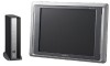
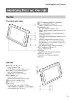
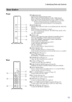
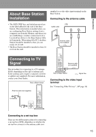
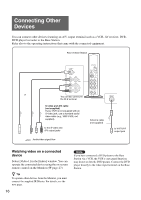
Base Station Front Rear qf qd qs Identifying Parts and Controls 1 WIRELESS LED Indicates the wireless function status. Blue: Connected with the Monitor on the 5 GHz channel. Green: Connected with the Monitor on the 2.4 GHz channel. Turns blue or green momentarily, then turns off for 3 seconds: Wireless communications are enabled, but wireless communication with the Monitor is not taking place. 1 2 NETWORK LED 2 Indicates the connection status to an external network, such as the Internet. 3 Green blinking: Attempting to connect. Green: Connected to the network. The LED blinks quickly when 4 data is transmitted. Off: Not connected. 3 NETAV LED 5 Indicates the connection status with the LocationFree device. Green quick blinking: NetAV authentication has failed. 6 Green slow blinking: Attempting to connect with NetAV. Green: Connected with NetAV. Umber blinking: Updating dynamic DNS. Umber: Dynamic DNS failure. Off: Not connected. Red: The Base Station is being initialized. 4 SETUP MODE LED Umber: The Base Station is in Setup mode. Umber blinking: Registration of a LocationFree device is available. 5 POWER LED (1 page 21) Green: The power is on. Red blinking: A malfunction has occurred. 6 POWER button (1 page 21) Turns the Base Station power on and off. 7 LAN port (1 page 19) Connect a LAN cable (not supplied). 8 BASE STATION RESET button (1 page 81) Initializes all settings on the Base Station to the factory defaults. 9 SETUP MODE button Press to register the LocationFree devices, or to make the Base Station settings without the Monitor. 7 0 IN 2 (AUDIO/VIDEO) terminal (1 page 16) Connect audio and video cables. 8 9 qa DC IN jack (1 page 20) Connect the AC power adapter (supplied). qs VHF/UHF jack (1 page 15) 0 Connect an antenna cable (not supplied). qd IN 1 (S-VIDEO/AUDIO/VIDEO) terminal (1 page 16) Connect audio cables and either a video or S-video cable. qa qf IR BLASTER port (1 page 17) Connect the IR Blaster (supplied). 13
-
 1
1 -
2
-
3
-
4
-
5
-
6
-
7
-
 8
8 -
 9
9 -
 10
10 -
 11
11 -
 12
12 -
 13
13 -
 14
14 -
 15
15 -
 16
16 -
 17
17 -
 18
18 -
19
-
20
-
21
-
22
-
23
-
24
-
25
-
26
-
27
-
28
-
29
-
30
-
31
-
32
-
33
-
34
-
35
-
36
-
37
-
38
-
39
-
40
-
41
-
42
-
43
-
44
-
45
-
46
-
47
-
48
-
49
-
50
-
51
-
52
-
53
-
54
-
55
-
56
-
57
-
58
-
59
-
60
-
61
-
62
-
63
-
64
-
65
-
66
-
67
-
68
-
69
-
70
-
71
-
72
-
73
-
74
-
75
-
76
-
77
-
78
-
79
-
80
-
81
-
82
-
83
-
84
-
85
-
86
-
87
-
88
-
89
-
90
-
91
-
92
-
93
-
94
-
95
-
96
 |
 |
