Sony PMW320K Product Manual (PMW320 Operating Instruction) - Page 24
VIDEO OUT connector BNC type, TC OUT timecode output connector
 |
View all Sony PMW320K manuals
Add to My Manuals
Save this manual to your list of manuals |
Page 24 highlights
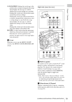
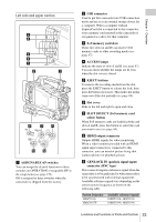
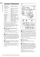
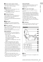
Chapter 1 Overview System frequency 1080/23.98P (PsF output) 1080/23.98P (Pulldown output) 720/59.94P 720/29.97P 720/23.98P 480/59.94i 480/29.97P 1080/50i 1080/25P 720/50P 720/25P 576/50i 576/25P Available reference signals 1080/23.98PsF, 480/59.94i 1080/59.94i, 480/59.94i 1080/59.94i, 720/59.94P, 480/59.94i 1080/59.94i, 720/59.94P, 480/59.94i 1080/59.94i, 720/59.94P, 480/59.94i 1080/59.94i, 480/59.94i 1080/59.94i, 480/59.94i 1080/50i, 576/50i 1080/50i, 576/50i 1080/50i, 720/50P, 576/50i 1080/50i, 720/50P, 576/50i 1080/50i, 576/50i 1080/50i, 576/50i (Genlock for the camera module supports horizontal sync signals only.) Use MAINTENANCE >GENLOCK in the setup menu to adjust the genlock H-phase (phase of horizontal sync signal). j TC IN (timecode input) connector (BNC type) To apply an external lock to the timecode of the camcorder, input the reference timecode. For details, see "Setting the Timecode" (page 61). k VIDEO OUT connector (BNC type) Outputs video signals for monitoring. The output signals can be selected either composite video or HD-Y depending on the setting of OPERATION >Input/Output >Output&i.LINK in the setup menu. l TC OUT (timecode output) connector (BNC type) To lock the timecode of an external VTR to the timecode of this camcorder, connect this connector to the external VTR's timecode input connector. Rear a TALLY (back tally) indicators (red) Light up during recording. They will not light if the TALLY switch is set to OFF. These indicators also flash to indicate warnings (see page 20). The tally indicator on the front of the viewfinder and the REC indication on the viewfinder screen light or flash in the same manner. For details, see "Operation Warnings" (page 149). b TALLY switch Set to ON to activate the TALLY indicator function. c EARPHONE jack (stereo, minijack) You can monitor the E-E sound during recording and playback sound during playback. When an alarm is indicated, you can hear the alarm sound through the earphone. Plugging an earphone into the jack automatically cuts off the built-in speaker. You can select monaural or stereo on MAINTENANCE >Audio in the setup menu. 24 Locations and Functions of Parts and Controls
-
 1
1 -
2
-
3
-
4
-
5
-
6
-
7
-
8
-
9
-
10
-
11
-
12
-
13
-
14
-
15
-
16
-
17
-
18
-
 19
19 -
 20
20 -
 21
21 -
 22
22 -
 23
23 -
 24
24 -
 25
25 -
 26
26 -
 27
27 -
 28
28 -
 29
29 -
30
-
31
-
32
-
33
-
34
-
35
-
36
-
37
-
38
-
39
-
40
-
41
-
42
-
43
-
44
-
45
-
46
-
47
-
48
-
49
-
50
-
51
-
52
-
53
-
54
-
55
-
56
-
57
-
58
-
59
-
60
-
61
-
62
-
63
-
64
-
65
-
66
-
67
-
68
-
69
-
70
-
71
-
72
-
73
-
74
-
75
-
76
-
77
-
78
-
79
-
80
-
81
-
82
-
83
-
84
-
85
-
86
-
87
-
88
-
89
-
90
-
91
-
92
-
93
-
94
-
95
-
96
-
97
-
98
-
99
-
100
-
101
-
102
-
103
-
104
-
105
-
106
-
107
-
108
-
109
-
110
-
111
-
112
-
113
-
114
-
115
-
116
-
117
-
118
-
119
-
120
-
121
-
122
-
123
-
124
-
125
-
126
-
127
-
128
-
129
-
130
-
131
-
132
-
133
-
134
-
135
-
136
-
137
-
138
-
139
-
140
-
141
-
142
-
143
-
144
-
145
-
146
-
147
-
148
-
149
-
150
-
151
-
152
-
153
-
154
-
155
-
156
-
157
-
158
-
159
-
160
-
161
-
162
-
163
-
164
-
165
-
166
-
167
-
168
-
169
-
170
-
171
 |
 |
