Sony SRR1000 Product Brochure (SRMASTER: SRR1000 Operation Manual) - Page 13
ASRMemory slot Fast flashing red light
 |
View all Sony SRR1000 manuals
Add to My Manuals
Save this manual to your list of manuals |
Page 13 highlights
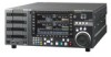
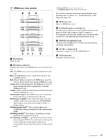
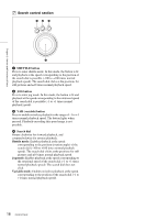
Chapter 2 Names and Functions of Parts A SRMemory slot section a Eject button Ejects a card. b SRMemory indicator Indicates the status of the SRMemory card inserted in the slot. Off: The SRMemory card is logically detached from the unit. Blue: An SRMemory card is connected to the unit and available for use. Red: Data is being recorded to the SRMemory card. Or, files are being copied from another SRMemory card. Green: Data is being read from the SRMemory card. Or, data is being read while copying files to another SRMemory card. Amber: Data is simultaneously being recorded to and read from the SRMemory card. Flashing blue light1): The SRMemory card is logically being attached to or detached from the unit. Flashing green light1): Data other than audio and video signals, such as file name changes, OK/NG/KEEP flag settings, write protection settings for files, is being written. Flashing purple light1): Files are being deleted or formatting is being performed from the maintenance menu. Flashing red light1): Salvaging or formatting is being performed in response to an error. Fast flashing red light1): A problem was detected while processing the SRMemory card. Eject or salvage the card or perform the appropriate operation as instructed by the message that appears on the control panel. 1) Flashing LED: Flashes at 1-second interval. Fast flashing LED: Flashes at 1/4-second interval. For details on salvage operations and formatting when problems have occurred, see "Troubleshooting" in the Appendix (page 56). c SRMemory slot Insert an SRMemory card. d On/Standby button and indicator Switches the unit between on and standby when the main power switch on the connector panel is turned on. The indicator is lit red in the standby state, and green in the on state. It is off when the main power switch is off. e PHONES (headphones) jack Accepts stereo headphones for monitoring audio during recording and playback. f LEVEL (volume) knob Adjusts the output level of the PHONES jack. g USB connectors Currently cannot be used. 13 Control Panel
-
 1
1 -
2
-
3
-
4
-
5
-
6
-
7
-
 8
8 -
 9
9 -
 10
10 -
 11
11 -
 12
12 -
 13
13 -
 14
14 -
 15
15 -
 16
16 -
 17
17 -
 18
18 -
19
-
20
-
21
-
22
-
23
-
24
-
25
-
26
-
27
-
28
-
29
-
30
-
31
-
32
-
33
-
34
-
35
-
36
-
37
-
38
-
39
-
40
-
41
-
42
-
43
-
44
-
45
-
46
-
47
-
48
-
49
-
50
-
51
-
52
-
53
-
54
-
55
-
56
-
57
-
58
-
59
-
60
-
61
-
62
-
63
-
64
-
65
-
66
-
67
-
68
-
69
-
70
 |
 |
