Sony SRR1000 Product Brochure (SRMASTER: SRR1000 Operation Manual) - Page 67
Hd Sdi Input A/b Connector, Hd Sdi Input Monitor A/b
 |
View all Sony SRR1000 manuals
Add to My Manuals
Save this manual to your list of manuals |
Page 67 highlights
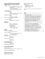
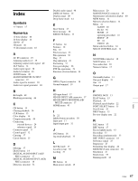
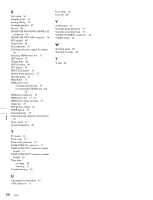
Index Symbols +/- button 15 Numerics 12-hour display 44 24-hour display 44 2D/3D 47 3D mode 46 75 Ω terminal switch 18 A AC IN connector 19 Adjusting audio level 39 Adjusting output video signal 40 ALT button 14 Audio input signal 38 Audio level meter 21 AUDIO menu 48 AUDIO MONITOR OUTPUT connector 19 Audio signal to monitor 38 Audio test signal generator 48 B Bit length 48 Blanking processing 46 C CH button 14 Chasing playback 34 CLR button 15 Color display 14 Compression mode 48 Connecting external devices 24 reference signal 26 Connector panel 17 Control panel 12 Copying 37 Cursor button 15 D Deleting 37 DIAG button 14 DIGITAL AUDIO INPUT (AES/ EBU) connector 17 DIGITAL AUDIO OUTPUT (AES/ EBU) connector 18 Directory structure 51 Disable audio signal 48 DISPLAY button 14 Display range 48 Drop frame mode 44 E Eject button 13 Error message 58 EXECUTE button 15 F F1 button 14 Features 10 File 22 File list screen 23 File operation 36 Flag 37 Flag indication 23 Formatting 57 Four-port display 20 FTP file operations 51 Function selection button 14 G GPIO (25-pin) connector 18 Ground terminal 19 H HD input board 17 HD SDI INPUT A/B connector 17 HD SDI INPUT MONITOR A/B/ MULTI connector 17 HOME menu 43 I In 22 Inhibit button operation 50 Input port 17 Input/output port 32 J JOG button 16 Jog mode playback 35 L LEVEL knob 13 Local key map 50 Locking 37 M M1 button 14 Main power switch 19 Main screen 20 MAINTENANCE connector 18 Maintenance information display 60 MEM button 14 Memory selection button 14 Menu 41 AUDIO 48 file list 36 HOME 43 operating procedure 41 SETUP 49 TC 44 VIDEO 46 Menu selection button 14 MULTI CONTROL knob 14 N NETWORK connector 18 NEXT button 15 Non-audio data 38 Numeric button 15 O On/standby button 13 One-port display 21 Out 22 Output port 17 P PHONES JACK 13 PLAY button 15 Playback 34 Playback speed display 22 PORT SELECT button 15 Preroll time 43 PREV button 15 Preview display area 22 R RCL button 15 REC button 15 Record inhibit mode 43 Recording 33 Recording simultaneously 33 REF. INPUT connector 18 Reference signal 25 Regenerate 27 Remaining time display 22 REMOTE (9-pin) connector 18 Resolution 47 Restrictions 55 Running mode 44 Index Index 67
-
 1
1 -
2
-
3
-
4
-
5
-
6
-
7
-
8
-
9
-
10
-
11
-
12
-
13
-
14
-
15
-
16
-
17
-
18
-
19
-
20
-
21
-
22
-
23
-
24
-
25
-
26
-
27
-
28
-
29
-
30
-
31
-
32
-
33
-
34
-
35
-
36
-
37
-
38
-
39
-
40
-
41
-
42
-
43
-
44
-
45
-
46
-
47
-
48
-
49
-
50
-
51
-
52
-
53
-
54
-
55
-
56
-
57
-
58
-
59
-
60
-
61
-
 62
62 -
 63
63 -
 64
64 -
 65
65 -
 66
66 -
 67
67 -
 68
68 -
 69
69 -
 70
70
 |
 |