Sony SRR1000 Product Brochure (SRMASTER: SRR1000 Operation Manual) - Page 17
Connector Panel
 |
View all Sony SRR1000 manuals
Add to My Manuals
Save this manual to your list of manuals |
Page 17 highlights
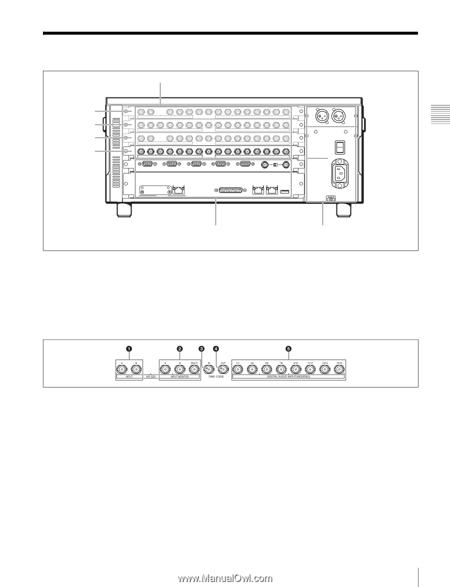
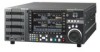
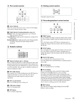
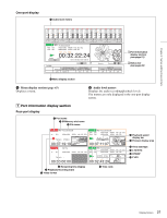
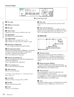
Connector Panel A Input/output ports (see page 17) Port A Port B Port C Port D Chapter 2 Names and Functions of Parts * At the time of shipment from the factory, no boards are connected to ports A to C. An output board is connected to port D. B Remote input/output section (see page 18) C Analog output/power supply section (see page 19) A Input/output ports There are the four ports A to D, and an input board or output board can be connected to each of them. At the time of shipment, an output board is connected to port D. Explanations in this operation manual use the configuration example of input boards (SRK-R201) HD Input board (SRK-R201) connected to ports A and C and output boards (SRK-R202) connected to ports B and D. a HD SDI INPUT A/B connectors Input the HD SDI video/audio signals. b HD SDI INPUT MONITOR A/B/MULTI connectors Output the input signals for a monitor. The MULTI connector currently cannot be used. c TIME CODE IN connector Inputs a time code generated by an external device. d TIME CODE OUT connector When the time code generator is synchronized to the external time code signals input via the TIME CODE IN connector, this outputs the external time codes input via the TIME CODE IN connector according to the ALT/[F3] (TC OUT) button setting in the TC menu. Outputs generated time code signals when the internal time code generator is generating time codes. e DIGITAL AUDIO INPUT (AES/EBU) connector Input the audio signals in AES/EBU format for channels 1 to 16. 17 Connector Panel
-
 1
1 -
2
-
3
-
4
-
5
-
6
-
7
-
8
-
9
-
10
-
11
-
 12
12 -
 13
13 -
 14
14 -
 15
15 -
 16
16 -
 17
17 -
 18
18 -
 19
19 -
 20
20 -
 21
21 -
 22
22 -
23
-
24
-
25
-
26
-
27
-
28
-
29
-
30
-
31
-
32
-
33
-
34
-
35
-
36
-
37
-
38
-
39
-
40
-
41
-
42
-
43
-
44
-
45
-
46
-
47
-
48
-
49
-
50
-
51
-
52
-
53
-
54
-
55
-
56
-
57
-
58
-
59
-
60
-
61
-
62
-
63
-
64
-
65
-
66
-
67
-
68
-
69
-
70
 |
 |