Sony SRR1000 Product Brochure (SRMASTER: SRR1000 Operation Manual) - Page 19
Analog output/power supply AUDIO MONITOR OUTPUT connectors, Main power switch
 |
View all Sony SRR1000 manuals
Add to My Manuals
Save this manual to your list of manuals |
Page 19 highlights
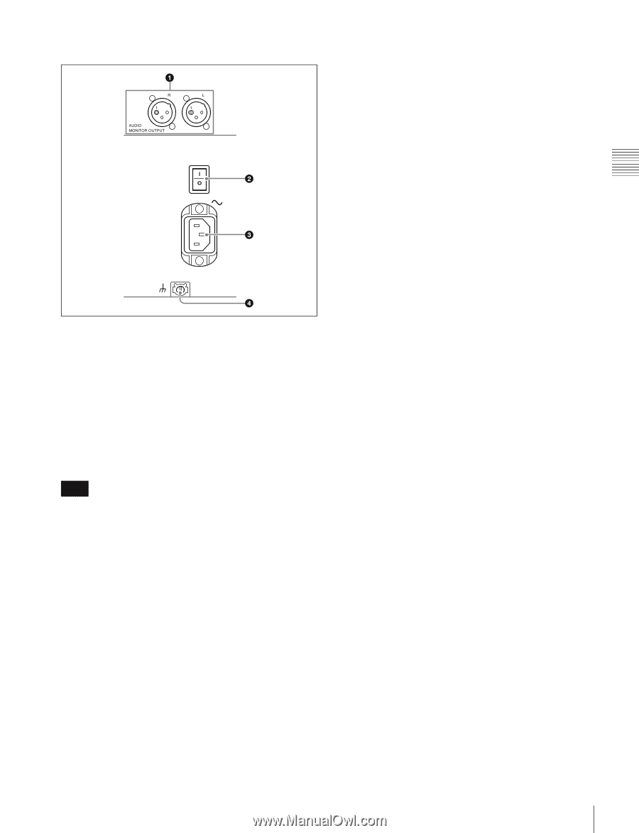
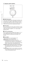
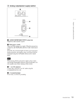
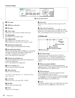
C Analog output/power supply section Chapter 2 Names and Functions of Parts a AUDIO MONITOR OUTPUT connectors Output the audio monitor signals. b Main power switch Turns on/off the main power supply. When the main power is turned on, the On/Standby indicator on the control panel lights. Normally, this switch should be left in the top (on) position during operation, and standby status switching should be performed using the On/Standby button on the control panel. Note When turning off the main power supply, always make sure that the On/Standby indicator on the front panel is lit red (standby state) before turning off the switch. c - AC IN connector Connect this connector to an AC outlet using the recommended power cord. d U Ground terminal If necessary, use this for grounding. 19 Connector Panel
-
 1
1 -
2
-
3
-
4
-
5
-
6
-
7
-
8
-
9
-
10
-
11
-
12
-
13
-
 14
14 -
 15
15 -
 16
16 -
 17
17 -
 18
18 -
 19
19 -
 20
20 -
 21
21 -
 22
22 -
 23
23 -
 24
24 -
25
-
26
-
27
-
28
-
29
-
30
-
31
-
32
-
33
-
34
-
35
-
36
-
37
-
38
-
39
-
40
-
41
-
42
-
43
-
44
-
45
-
46
-
47
-
48
-
49
-
50
-
51
-
52
-
53
-
54
-
55
-
56
-
57
-
58
-
59
-
60
-
61
-
62
-
63
-
64
-
65
-
66
-
67
-
68
-
69
-
70
 |
 |