Sony SRR1000 Product Brochure (SRMASTER: SRR1000 Operation Manual) - Page 29
Superimposing Character Information
 |
View all Sony SRR1000 manuals
Add to My Manuals
Save this manual to your list of manuals |
Page 29 highlights
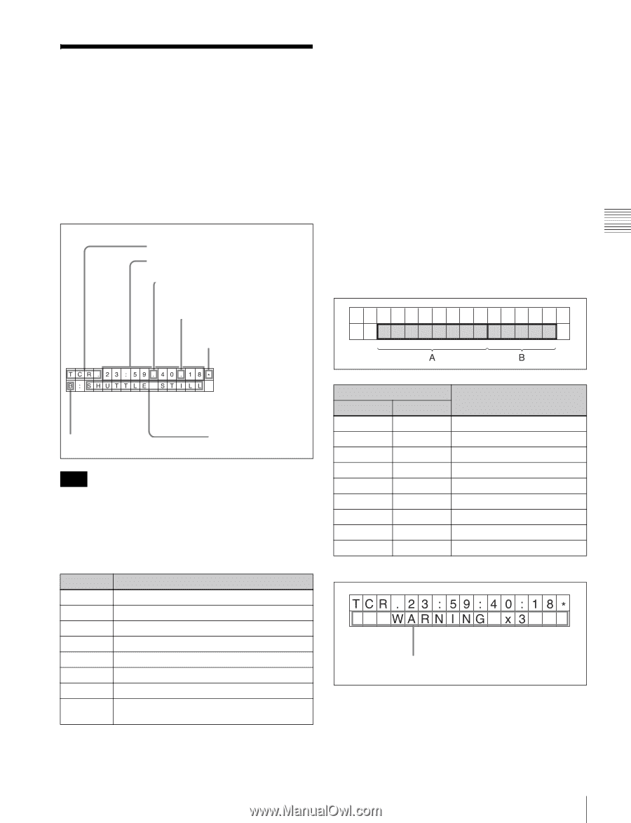
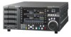
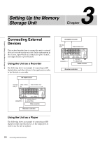
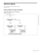
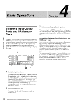
Chapter 3 Setting Up the Memory Storage Unit Superimposing Character Information To superimpose characters representing the time data, operation mode, and other information on output signals, set the ALT/[F10] (CHAR ON) buttons to On in the TC menu. Character information is superimposed on signals output from the SD/HD SDI MONITOR connector. Contents of superimposed data a Type of time data Time data b Drop frame mark of the time code reader c Drop frame mark of the time code generator d Field mark of the VITC data b Drop frame mark of the time code reader ".": Drop frame mode ":": Non-drop frame mode c Drop frame mark of the time code generator ".": Drop frame mode ":": Non-drop frame mode d Field mark of the VITC data " " (blank space): When displaying fields 1 and 3 "*": When displaying fields 2 and 4 e Port Indicates the output port. f Operation mode The contents are divided into blocks A and B as shown in the following table. Block A: Operation mode Block B: Lock state or playback speed e Port f Operation mode Note The example above shows the factory-set contents of data. If you change the setting of the ALT/[F7] - [F3] (INFO SEL) buttons in the TC menu, a different type of time data can also be displayed on the second line. a Types of time data Indication Meaning TCR Time code data of LTC reader UBR User bit data of LTC reader TCR. Time code data of VITC reader UBR. User bit data of VITC reader TCG Time code data of time code generator UBG User bit data of time code generator TM1 Time counter value that can be preset. TM2 Time counter value for which the beginning of the file is 0. Indication Block A Block B Operation mode STOP PLAY PLAY LOCK Stop mode Playback mode (unlocked) Playback mode (locked) JOG JOG JOG STILL FWD REV Still-picture jog mode Forward jog Reverse jog SHUTTLE VAR PORT (Speed) (Speed) CLOSE Shuttle mode Variable mode Port closed To display an error/warning message The number of error/warning message occurrences Set the ALT/[F7] - [F3] (INFO SEL) buttons to any value other than [Time]. The number of error/warning message occurrences flashes on the second line. 29 Superimposing Character Information
-
 1
1 -
2
-
3
-
4
-
5
-
6
-
7
-
8
-
9
-
10
-
11
-
12
-
13
-
14
-
15
-
16
-
17
-
18
-
19
-
20
-
21
-
22
-
23
-
 24
24 -
 25
25 -
 26
26 -
 27
27 -
 28
28 -
 29
29 -
 30
30 -
 31
31 -
 32
32 -
 33
33 -
 34
34 -
35
-
36
-
37
-
38
-
39
-
40
-
41
-
42
-
43
-
44
-
45
-
46
-
47
-
48
-
49
-
50
-
51
-
52
-
53
-
54
-
55
-
56
-
57
-
58
-
59
-
60
-
61
-
62
-
63
-
64
-
65
-
66
-
67
-
68
-
69
-
70
 |
 |