Sony SRR1000 Product Brochure (SRMASTER: SRR1000 Operation Manual) - Page 14
Menu control MULTI CONTROL knob
 |
View all Sony SRR1000 manuals
Add to My Manuals
Save this manual to your list of manuals |
Page 14 highlights
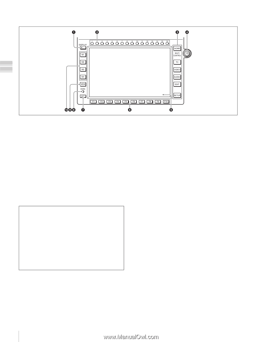
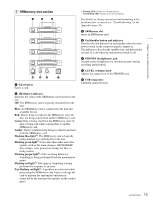
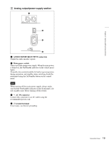
B Menu control section Chapter 2 Names and Functions of Parts a DISPLAY button Displays the video signal on the entire display. b CH (channel) selection buttons Select the channel to adjust the audio recording/playback level or to select an audio input. c Menu selection buttons (page 41) Select the menu screen to display on the display. Currently, the EDIT button cannot be used. d MULTI CONTROL knob Sets the audio recording/playback levels, sets menus, selects files, etc. e Color display (page 20) Note on faulty pixels on the LCD panel The LCD panel fitted to this unit is manufactured with high precision technology, giving a functioning pixel ratio of at least 99.99%. Thus a very small proportion of pixels maybe "stuck", either always off (black), always on (red, green, or blue), or flashing. In addition, over a long period of use, because of the physical characteristics of the liquid crystal display, such "stuck" pixels may appear spontaneously. These problems are not a malfunction. Note that any such problems have no effect on recorded data. f Function selection buttons (F1 to F10) Select a function displayed on the menu screen. g ALT (alternative) button Changes the menu screen display. h DIAG (diagnostic) button Displays the DIAG menu when pressed together with the SFT button. i MEM button Currently cannot be used. j Memory selection buttons (M1 to M4) (page 32) Select the SRMemory card to use. 14 Control Panel
-
 1
1 -
2
-
3
-
4
-
5
-
6
-
7
-
8
-
 9
9 -
 10
10 -
 11
11 -
 12
12 -
 13
13 -
 14
14 -
 15
15 -
 16
16 -
 17
17 -
 18
18 -
 19
19 -
20
-
21
-
22
-
23
-
24
-
25
-
26
-
27
-
28
-
29
-
30
-
31
-
32
-
33
-
34
-
35
-
36
-
37
-
38
-
39
-
40
-
41
-
42
-
43
-
44
-
45
-
46
-
47
-
48
-
49
-
50
-
51
-
52
-
53
-
54
-
55
-
56
-
57
-
58
-
59
-
60
-
61
-
62
-
63
-
64
-
65
-
66
-
67
-
68
-
69
-
70
 |
 |