Sony SRR1000 Product Brochure (SRMASTER: SRR1000 Operation Manual) - Page 60
Warning Messages, To display warning messages as pop-ups
 |
View all Sony SRR1000 manuals
Add to My Manuals
Save this manual to your list of manuals |
Page 60 highlights
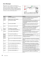
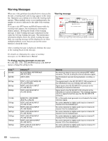
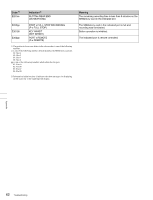
Warning Messages When one of the problems described below is detected by the unit, a warning mark and message appear on the status bar. Operation can continue even when the warning mark appears. When multiple errors occur simultaneously, the number of errors is indicated to the right of the warning mark. If you press the SFT button and DIAG button while the warning mark appears, the maintenance information display appears, showing the details of the warning message. A short warning message is displayed on the status bar for long warning messages. The maintenance information display shows the whole warning message. Only one warning message will be displayed even when multiple problems occur, but you can use the cursor buttons to check the errors. After a warning message is displayed, eliminate the cause of the warning based on the message. For details on eliminating the causes of warning messages, see the Maintenance Manual. To display warning messages as pop-ups Press the [F2] - [F7] - [F3] (WARN) buttons in the SETUP menu to change the setting to On. Code 1) 010100 020100 Indication2) NO EXTERNAL REFERENCE (NO EXT REF) LOST LOCK 0601pp 0801pp 0802pp PORT x SDI A-B PHASE NG (P-x A-B PHASE) PORT x NO SDI-A INPUT (P-x NO SDI-A) PORT x NO SDI-B INPUT (P-x NO SDI-B) 110100 1901pp 1A01pp 1B01pp 1C01pp 1D01pp 1E01pp AUDIO PLL UNLOCKED (AUD PLL UNLCK) PORT x NO A1/A2 INPUT (P-x NO A1/A2) PORT x NO A3/A4 INPUT (P-x NO A3/A4) PORT x NO A5/A6 INPUT (P-x NO A5/A6) PORT x NO A7/A8 INPUT (P-x NO A7/A8) PORT x NO A9/A10 INPUT (P-x NO A9/10) PORT x NO A11/A12 INPUT (P-x NO A11/12) Warning message Meaning No reference signal is input to the selected REF. INPUT connector. The unit is using the internal reference signal. Synchronization was lost during playback, recording, or editing. The signals input to the HD SDI INPUT A/B connector at the indicated port are out of phase with each other. Signal input to the HD SDI INPUT A connector at the indicated port cannot be detected. Signal input to the HD SDI INPUT B connector at the indicated port cannot be detected. This message appears only for a signal format that uses the HD SDI INPUT B connector. PLL of the audio clock generator is not locked to the video reference signal. No carrier detected on digital audio input on channel 1/ channel 2 for the indicated port. No carrier detected on digital audio input on channel 3/ channel 4 for the indicated port. No carrier detected on digital audio input on channel 5/ channel 6 for the indicated port. No carrier detected on digital audio input on channel 7/ channel 8 for the indicated port. No carrier detected on digital audio input on channel 9/ channel 10 for the indicated port. No carrier detected on digital audio input on channel 11/ channel 12 for the indicated port. Appendix 60 Troubleshooting
-
 1
1 -
2
-
3
-
4
-
5
-
6
-
7
-
8
-
9
-
10
-
11
-
12
-
13
-
14
-
15
-
16
-
17
-
18
-
19
-
20
-
21
-
22
-
23
-
24
-
25
-
26
-
27
-
28
-
29
-
30
-
31
-
32
-
33
-
34
-
35
-
36
-
37
-
38
-
39
-
40
-
41
-
42
-
43
-
44
-
45
-
46
-
47
-
48
-
49
-
50
-
51
-
52
-
53
-
54
-
 55
55 -
 56
56 -
 57
57 -
 58
58 -
 59
59 -
 60
60 -
 61
61 -
 62
62 -
 63
63 -
 64
64 -
 65
65 -
66
-
67
-
68
-
69
-
70
 |
 |
