Sony SRR1000 Product Brochure (SRMASTER: SRR1000 Operation Manual) - Page 18
Remote input/output HD Output board SRK-R202
 |
View all Sony SRR1000 manuals
Add to My Manuals
Save this manual to your list of manuals |
Page 18 highlights
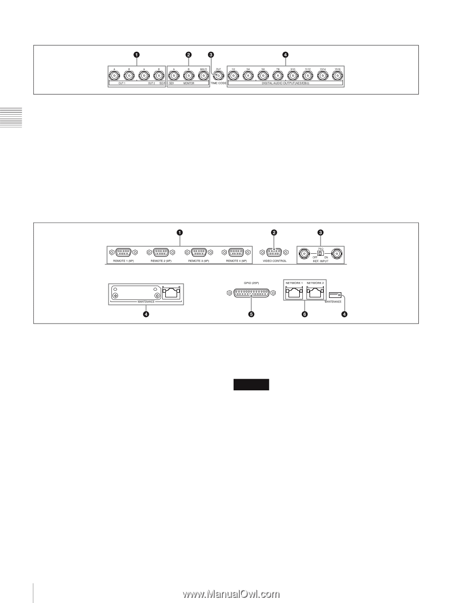
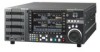
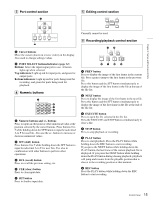
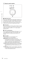
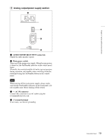
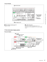
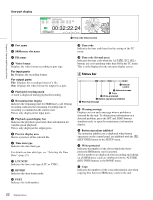
HD Output board (SRK-R202) a SD/HD SDI OUT A/B connectors Output two sets of SD SDI or HD SDI video/audio signals. Currently, only HD SDI signals are supported. b SD/HD SDI MONITOR A/B/MULTI connectors Output the output signals for a monitor. Time data and other character signals are superimposed and then output when ALT/[F10] (CHAR ON) in the TC menu is set to On. The MULTI connector currently cannot be used. Currently, only HD SDI signals are supported. c TIME CODE OUT connector Outputs the playback time code. d DIGITAL AUDIO OUTPUT (AES/EBU) connector Output the audio signals in AES/EBU format for channels 1 to 16. B Remote input/output section Chapter 2 Names and Functions of Parts a REMOTE 1 to 4 (9-pin) connectors To control the unit from an external device, connect it to the external device with a remote control cable that has a 9-pin connector. The Sony 9-pin VTR protocol and Sony 9-pin Disk protocol are supported. b VIDEO CONTROL connector Currently cannot be used. c REF. INPUT connectors and 75 Ω terminal switch Input the reference video signal of the selected field frequency. Input an HD tri-level SYNC signal or SD black burst signal. A loop-through connection is also possible. Set the 75 Ω terminal switch to OFF if you are using a loop-through connection, and set it to ON if you are not using a loopthrough connection. d MAINTENANCE connector Used by the administrator. This is not for normal use. e GPIO (25-pin) connector Currently cannot be used. f NETWORK 1/2 connectors Accepts a network cable for monitoring the unit by SNMP, configuring or checking the unit via HTTP, transferring files via FTP, etc. CAUTION • For safety, do not connect the connector for peripheral device wiring that might have excessive voltage to this connector. Follow the instructions for this port. • When you connect the network cable of the unit to peripheral device, use a shielded-type cable to prevent malfunction due to radiation noise. 18 Connector Panel
-
 1
1 -
2
-
3
-
4
-
5
-
6
-
7
-
8
-
9
-
10
-
11
-
12
-
 13
13 -
 14
14 -
 15
15 -
 16
16 -
 17
17 -
 18
18 -
 19
19 -
 20
20 -
 21
21 -
 22
22 -
 23
23 -
24
-
25
-
26
-
27
-
28
-
29
-
30
-
31
-
32
-
33
-
34
-
35
-
36
-
37
-
38
-
39
-
40
-
41
-
42
-
43
-
44
-
45
-
46
-
47
-
48
-
49
-
50
-
51
-
52
-
53
-
54
-
55
-
56
-
57
-
58
-
59
-
60
-
61
-
62
-
63
-
64
-
65
-
66
-
67
-
68
-
69
-
70
 |
 |