TP-Link TL-SG2424P TL-SG2424P V1 User Guide 1910010774
TP-Link TL-SG2424P Manual
 |
View all TP-Link TL-SG2424P manuals
Add to My Manuals
Save this manual to your list of manuals |
TP-Link TL-SG2424P manual content summary:
- TP-Link TL-SG2424P | TL-SG2424P V1 User Guide 1910010774 - Page 1
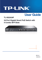
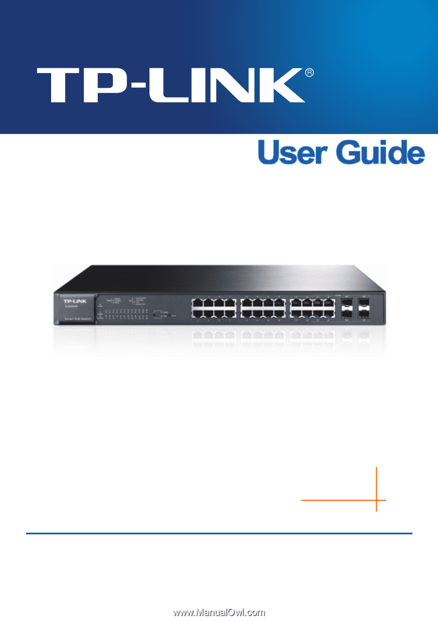
TL-SG2424P 24-Port Gigabit Smart PoE Switch with 4 Combo SFP Slots REV1.0.0 1910010774 - TP-Link TL-SG2424P | TL-SG2424P V1 User Guide 1910010774 - Page 2
TP-LINK TECHNOLOGIES CO., LTD. Copyright © 2013 TP-LINK TECHNOLOGIES CO., LTD. All rights reserved. http://www.tp-link and used in accordance with the instruction manual, may cause harmful interference to party responsible for compliance could void the user's authority to operate the equipment. CE - TP-Link TL-SG2424P | TL-SG2424P V1 User Guide 1910010774 - Page 3
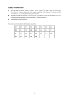
from the power source. Don't disassemble the product, or make repairs yourself. You run the risk of electric shock and voiding the limited warranty. If you need service, please contact us. Avoid water and wet locations. This product can be used in the following countries: AT BG BY CA CZ - TP-Link TL-SG2424P | TL-SG2424P V1 User Guide 1910010774 - Page 4
System Time ...12 4.1.4 Daylight Saving Time 13 4.1.5 System IP...15 4.2 User Management ...16 4.2.1 User Table...16 4.2.2 User Config ...16 4.3 System Tools ...18 4.3.1 Config Restore 18 4.3.2 Config Backup 18 4.3.3 Firmware Upgrade 19 4.3.4 System Reboot 20 4.3.5 System Reset 20 4.4 Access - TP-Link TL-SG2424P | TL-SG2424P V1 User Guide 1910010774 - Page 5
46 5.4.3 Dynamic Address 47 5.4.4 Filtering Address 49 5.5 DHCP Filtering...50 Chapter 6 VLAN...54 6.1 802.1Q VLAN...55 6.1.1 VLAN Config ...57 6.1.2 Port Config ...59 6.2 Application Example for 802.1Q VLAN 61 Chapter 7 Spanning Tree ...63 7.1 STP Config ...68 7.1.1 STP Config...68 7.1.2 STP - TP-Link TL-SG2424P | TL-SG2424P V1 User Guide 1910010774 - Page 6
9.2.1 Rate Limit...107 9.2.2 Storm Control 108 9.3 Voice VLAN ...110 9.3.1 Global Config 112 9.3.2 Port Config ...112 9.3.3 OUI Config ...114 Chapter 10 PoE ...116 10.1 PoE Config ...116 10.1.1 PoE Config...117 10.1.2 PoE Profile ...118 10.2 PoE Time-Range ...119 10.2.1 Time-Range Summary 119 10 - TP-Link TL-SG2424P | TL-SG2424P V1 User Guide 1910010774 - Page 7
.1.2 SNMP View ...125 11.1.3 SNMP Group 126 11.1.4 SNMP User ...127 11.1.5 SNMP Community 129 11.2 Notification...131 11.3 Chapter 12 LLDP ...138 12.1 Basic Config ...142 12.1.1 Global Config 142 12.1.2 Port Config ...143 12.2 Device Info...144 12.2.1 Local Info ...144 12.2.2 Neighbor Info 145 - TP-Link TL-SG2424P | TL-SG2424P V1 User Guide 1910010774 - Page 8
13.4.2 Tracert...160 Appendix A: Specifications ...162 Appendix B: Configuring the PCs 163 Appendix C: Glossary...165 IX - TP-Link TL-SG2424P | TL-SG2424P V1 User Guide 1910010774 - Page 9
items should be found in your box: One 24-Port Gigabit Smart PoE Switch with 4 Combo SFP Slots One power cord Two mounting brackets and other fittings Installation Guide Resource CD for TL-SG2424P switch, including: This User Guide Other Helpful Information Note: Make sure that the - TP-Link TL-SG2424P | TL-SG2424P V1 User Guide 1910010774 - Page 10
Chapter 1 About this Guide This User Guide contains information for setup and management of TL-SG2424P 24-Port Gigabit Smart PoE Switch with 4 Combo SFP Slots. Please read this guide carefully before operation. 1.1 Intended Readers This Guide is intended for network managers familiar with IT - TP-Link TL-SG2424P | TL-SG2424P V1 User Guide 1910010774 - Page 11
security measures for the login to enhance the configuration management security. This module is used to configure basic functions of the switch. Here mainly introduces: Port: Configure the basic features for the port. LAG: Configure Link Aggregation Group. LAG is to combine a number of - TP-Link TL-SG2424P | TL-SG2424P V1 User Guide 1910010774 - Page 12
PoE function for the switch to supply power for PD devices. Here mainly introduces: PoE Config: Configure PoE function globally. PoE Time-Range: Configure the effective time for PoE port to supply power.. Chapter 11 SNMP This module is used to configure SNMP function to provide a management - TP-Link TL-SG2424P | TL-SG2424P V1 User Guide 1910010774 - Page 13
for choosing the TL-SG2424P 24-Port Gigabit Smart PoE Switch with 4 Combo SFP Slots! 2.1 Overview of the Switch Designed for workgroups and departments, TL-SG2424P from TP-LINK provides wire-speed performance and abundant layer 2 management features. It provides a variety of service features and - TP-Link TL-SG2424P | TL-SG2424P V1 User Guide 1910010774 - Page 14
module. By default, the Speed and Duplex mode of SFP port is 1000MFD. LEDs TL-SG2424P has a LED mode switch button which is for switching the LED status indication. When the Speed LED is on, the port LED is indicating the data transmission rate. When the PoE LED is on, the port LED is indicating - TP-Link TL-SG2424P | TL-SG2424P V1 User Guide 1910010774 - Page 15
PoE power supply is provided on the port. 2.3.2 Rear Panel The rear panel of TL-SG2424P features a power socket and a Grounding Terminal (marked with ). Figure 2-2 Rear Panel Grounding Terminal: TL-SG2424P already comes with Lightning Protection Mechanism. You can also ground the switch through - TP-Link TL-SG2424P | TL-SG2424P V1 User Guide 1910010774 - Page 16
default address http://192.168.0.1 in the address field of the browser, then press the Enter key. Figure 3-1 Web-browser Tips: To log in to the switch, the IP the switch. The IP address is 192.168.0.x ("x" is any number from 2 to 254), Subnet Mask is 255.255.255.0. For the detailed instructions as - TP-Link TL-SG2424P | TL-SG2424P V1 User Guide 1910010774 - Page 17
Figure 3-3 Main Setup-Menu Note: Clicking Apply can only make the new configurations effective before the switch is rebooted. If you want to keep the configurations effective even the switch is rebooted, please click Save Config. You are suggested to click Save Config before cutting off the power or - TP-Link TL-SG2424P | TL-SG2424P V1 User Guide 1910010774 - Page 18
Saving Time and System IP pages. 4.1.1 System Summary On this page you can view the port connection status and the system information. The port status diagram shows the working status of 24 10/100/1000Mbps RJ45 ports and 4 SFP ports of the switch. Ports labeled as 1-24 are 10/100/1000Mbps RJ45 - TP-Link TL-SG2424P | TL-SG2424P V1 User Guide 1910010774 - Page 19
the speed of 100Mbps. When the cursor moves on the port, the detailed information of the port will be displayed. Port Info Figure 4-2 Port Information Port: Type: Speed: Status: Displays the port number of the switch. Displays the type of the port. Displays the maximum transmission rate of the - TP-Link TL-SG2424P | TL-SG2424P V1 User Guide 1910010774 - Page 20
sending packets on this port. 4.1.2 Device Description On this page you can configure the description of the switch, including device name, the switch is running. On this page you can configure the system time and the settings here will be used for other time-based functions. You can manually set - TP-Link TL-SG2424P | TL-SG2424P V1 User Guide 1910010774 - Page 21
manually. Get Time from NTP Server: Synchronize with PC'S Clock: When this option is selected, you can configure the time zone and the IP Address for the NTP server. The switch restored to the default when the switch is restarted and you need to reconfigure the system time of the switch. 2. When - TP-Link TL-SG2424P | TL-SG2424P V1 User Guide 1910010774 - Page 22
Choose the menu System→System Info→Daylight Saving Time to load the following page. Figure 4-6 Daylight Saving Time The following entries are displayed on this screen: DST Config DST Status: Enable or disable the DST. Predefined Mode: Recurring Mode: Date Mode: Select a predefined DST - TP-Link TL-SG2424P | TL-SG2424P V1 User Guide 1910010774 - Page 23
. However, if another VLAN is created and set to be the Management VLAN, you may have to reconnect the management station to a port that is a member of the Management VLAN. IP Address: Enter the system IP of the switch. The default system IP is 192.168.0.1 and you can change it appropriate to your - TP-Link TL-SG2424P | TL-SG2424P V1 User Guide 1910010774 - Page 24
cannot be configured. 5. By default, the default IP address is 192.168.0.1. 4.2 User Management User Management functions to configure the user name and password for users to log on to the Web management page with a certain access level so as to protect the settings of the switch from being randomly - TP-Link TL-SG2424P | TL-SG2424P V1 User Guide 1910010774 - Page 25
Select the desired entry to delete the corresponding user information. It is multi-optional The current user information can't be deleted. User ID, Name, Access Level and status: Operation: Displays the current user ID, user name, access level and user status. Click the Edit button of the desired - TP-Link TL-SG2424P | TL-SG2424P V1 User Guide 1910010774 - Page 26
4.3 System Tools The System Tools function, allowing you to manage the configuration file of the switch, can be implemented on Config Restore, Config Backup, Firmware Upgrade, System Reboot and System Reset pages. 4.3.1 Config Restore On this page you can upload a backup configuration file to - TP-Link TL-SG2424P | TL-SG2424P V1 User Guide 1910010774 - Page 27
. Please wait without any operation. 4.3.3 Firmware Upgrade The switch system can be upgraded via the Web management page. To upgrade the system is to get more functions and better performance. Go to http://www.tp-link.com to download the updated firmware. Choose the menu System→System Tools - TP-Link TL-SG2424P | TL-SG2424P V1 User Guide 1910010774 - Page 28
On this page you can reboot the switch and return to the login page. Please page you can reset the switch to the default. All the settings will be cleared after the switch is reset. Choose the : After the system is reset, the switch will be reset to the default and all the settings will be cleared. - TP-Link TL-SG2424P | TL-SG2424P V1 User Guide 1910010774 - Page 29
the control mode for users to log on to the Web management page. IP-based: Select this option to limit the IP-range of the users for login. MAC-based: Select this option to limit the MAC Address of the users for login. Port-based: Select this option to limit the ports for login. These fields - TP-Link TL-SG2424P | TL-SG2424P V1 User Guide 1910010774 - Page 30
provides the following services: 1. Authenticate the users and the servers based user to replace the default key pair. After SSL is effective, you can log on to the Web management page via https://192.168.0.1. For the first time you use HTTPS connection to log into the switch with the default - TP-Link TL-SG2424P | TL-SG2424P V1 User Guide 1910010774 - Page 31
work. 2. The SSL certificate and key downloaded will not take effect until the switch is rebooted. 3. To establish a secured connection using https, please enter https:// to a telnet connection, but essentially the old telnet remote management method is not safe, because the password and data - TP-Link TL-SG2424P | TL-SG2424P V1 User Guide 1910010774 - Page 32
authentication. This switch supports SSH server and you can log on to the switch via SSH the supported protocol. Protocol V2: Select Enable/Disable SSH V2 to be the supported The default value is 5. Key Download Key Type: Select the type of SSH Key to download. The switch supports three - TP-Link TL-SG2424P | TL-SG2424P V1 User Guide 1910010774 - Page 33
downloaded, the user's original key of the same type will be replaced. The wrong uploaded file will result in the SSH access to the switch via Password interface of PuTTY. Enter the IP address of the switch into Host Name field; keep the default value 22 in the Port field; select SSH as the - TP-Link TL-SG2424P | TL-SG2424P V1 User Guide 1910010774 - Page 34
Application Example 2 for SSH: Network Requirements 1. Log on to the switch via password authentication using SSH and the SSH function is enabled on the switch. 2. PuTTY client software is recommended. Configuration Procedure 1. Select the key type and key length, and generate SSH key. Note: 1. - TP-Link TL-SG2424P | TL-SG2424P V1 User Guide 1910010774 - Page 35
3. On the Web management page of the switch, download the public key file saved in the computer to the switch. Note: 1. 1. The key type should accord with the type of the key file. 2. 2. The SSH key downloading cannot be interrupted. 4. Download the private key file to SSH client software. 27 - TP-Link TL-SG2424P | TL-SG2424P V1 User Guide 1910010774 - Page 36
and private key are downloaded, please log on to the interface of PuTTY and enter the IP address for login. After successful authentication, please enter the login user name. If you log on to the switch without entering password, it indicates that the key has been successfully downloaded. Return to - TP-Link TL-SG2424P | TL-SG2424P V1 User Guide 1910010774 - Page 37
the basic functions of the switch, including four submenus: Port, LAG, Traffic Monitor and MAC Address. 5.1 Port The Port function, allowing you to configure the basic features for the port, is implemented on the Port Config, Port Mirror, Port Security, Port Isolation and Loopback Detection pages - TP-Link TL-SG2424P | TL-SG2424P V1 User Guide 1910010774 - Page 38
support auto-negotiation. Allows you to Enable/Disable the Flow Control feature. When Flow Control is enabled, the switch can synchronize the speed with its peer to avoid the packet loss caused by congestion. Displays the LAG number which the port belongs to. Note: 1. The switch cannot be managed - TP-Link TL-SG2424P | TL-SG2424P V1 User Guide 1910010774 - Page 39
this screen: Mirror Group Number: Select the mirror group number you want to configure. Mirroring Port Mirroring Port: Select the mirroring port number. Mirrored Port Port Select: Click the Select button to quick-select the corresponding port based on the port number you entered. 31 - TP-Link TL-SG2424P | TL-SG2424P V1 User Guide 1910010774 - Page 40
to generate the cheating MAC address and quickly occupy the MAC Address Table. When the MAC Address Table is full, the switch will broadcast the packets to all the ports. At this moment, the attacker can obtain the network information via various sniffers and attacks. When the MAC Address Table is - TP-Link TL-SG2424P | TL-SG2424P V1 User Guide 1910010774 - Page 41
cleared after the switch is rebooted. Permanent: When Permanent mode is selected, the learned MAC address will be out of the influence of the aging time and can only be deleted manually. The learned entries will be saved even the switch is rebooted. Select Enable/Disable the Port Security feature - TP-Link TL-SG2424P | TL-SG2424P V1 User Guide 1910010774 - Page 42
traffic flow to improve the network security by forbidding the port to forward packets to the ports that are not on its forward portlist. Choose the menu Switching→Port→Port Isolation to load the following page. Figure 5-5 Port Isolation Config The following entries are displayed on this screen - TP-Link TL-SG2424P | TL-SG2424P V1 User Guide 1910010774 - Page 43
detect loops using loopback detection packets. When a loop is detected, the switch will display an alert or further block the corresponding port according to the port configuration. Choose the menu Switching→Port→LoopbackDetection to load the following page. Figure 5-1 Loopback Detection Config The - TP-Link TL-SG2424P | TL-SG2424P V1 User Guide 1910010774 - Page 44
Time : Web Refresh Status: Web Refresh Interval: Port Config Port Select: Select: Port: Status: Operation Mode: Recovery Mode: Loop Status: Block Status: LAG: Manual Recover: Set a Loopback Detection interval between 1 and 1000 seconds. By default, it's 30 seconds. Time after which the blocked - TP-Link TL-SG2424P | TL-SG2424P V1 User Guide 1910010774 - Page 45
port is 2000Mbps counting the up-linked speed of 1000Mbps and the down-linked speed of 1000Mbps. 2. The traffic load of the LAG will be balanced among the ports can view the information of the current LAG of the switch. Choose the menu Switching→LAG→LAG Table to load the following page. Figure 5-6 - TP-Link TL-SG2424P | TL-SG2424P V1 User Guide 1910010774 - Page 46
, the Aggregate Arithmetic will apply to the source and destination IP addresses of the packets. LAG Table Select: Select the page, you can manually configure the LAG. The LACP feature is disabled for the member ports of the manually added Static LAG. Choose the menu Switching→LAG→Static LAG to - TP-Link TL-SG2424P | TL-SG2424P V1 User Guide 1910010774 - Page 47
Control Protocol) is defined in IEEE802.3ad and enables the dynamic link aggregation and disaggregation by exchanging LACP packets with its partner. The switch can dynamically group similarly configured ports into a single logical link, which will highly extend the bandwidth and flexibly balance the - TP-Link TL-SG2424P | TL-SG2424P V1 User Guide 1910010774 - Page 48
number is preferred. After an aggregation group is established, the selected ports can be aggregated together as one port to transmit packets. On this page, you can configure the LACP feature of the switch. Choose the menu Switching→LAG→LACP Config to load the following page. Figure 5-9 LACP Config - TP-Link TL-SG2424P | TL-SG2424P V1 User Guide 1910010774 - Page 49
pages. 5.3.1 Traffic Summary Traffic Summary screen displays the traffic information of each port, which facilitates you to monitor the traffic and analyze the network abnormity. Choose the menu Switching→Traffic Monitor→Traffic Summary to load the following page. Figure 5-10 Traffic Summary - TP-Link TL-SG2424P | TL-SG2424P V1 User Guide 1910010774 - Page 50
view the detailed traffic statistics of the port. 5.3.2 Traffic Statistics Traffic Statistics screen displays the detailed traffic information of each port, which facilitates you to monitor the traffic and locate faults promptly. Choose the menu Switching→Traffic Monitor→Traffic Statistics to load - TP-Link TL-SG2424P | TL-SG2424P V1 User Guide 1910010774 - Page 51
. The error frames are not counted in. Unicast: Displays the number of good unicast packets received or transmitted on the port. The error frames are not counted in. Alignment Errors: Displays the number of the received packets that have a bad Frame Check Sequence (FCS) with a non- - TP-Link TL-SG2424P | TL-SG2424P V1 User Guide 1910010774 - Page 52
MAC address of the packets. Address Table contains the port-based MAC address information, which is the base for the switch to forward packets quickly. The entries in the Address Table can be updated by auto-learning or configured manually. Most the entries are generated and updated by auto - TP-Link TL-SG2424P | TL-SG2424P V1 User Guide 1910010774 - Page 53
the filtering address entries only. Address Table MAC Address: Displays the MAC address learned by the switch. VLAN ID: Displays the corresponding VLAN ID of the MAC address. Port: Displays the corresponding Port number of the MAC address. Type: Displays the Type of the MAC address. 45 - TP-Link TL-SG2424P | TL-SG2424P V1 User Guide 1910010774 - Page 54
removed manually, independent of the aging time. In the stable networks, the static MAC address entries can facilitate the switch to be bound. VLAN ID: Enter the corresponding VLAN ID of the MAC address. Port: Select a port from the pull-down list to be bound. Search Option Search Option: - TP-Link TL-SG2424P | TL-SG2424P V1 User Guide 1910010774 - Page 55
2. If the MAC address of a device has been added to the Static Address Table, connecting the device to another port will cause its address not to be recognized dynamically by the switch. Therefore, please ensure the entries in the Static Address Table are correct and valid. 3. The MAC address in the - TP-Link TL-SG2424P | TL-SG2424P V1 User Guide 1910010774 - Page 56
Dynamic Address Table. MAC: Enter the MAC address of your desired entry. VLAN ID: Enter the VLAN ID number of your desired entry. Port: Enter the Port number of your desired entry. Dynamic Address Table Select: Select the entry to delete the dynamic address or to bind the MAC address to - TP-Link TL-SG2424P | TL-SG2424P V1 User Guide 1910010774 - Page 57
switch. It is recommended to keep the default value. 5.4.4 Filtering Address The filtering address is to forbid the undesired packets to be forwarded. The filtering address can be added or removed manually on all the ports in the corresponding VLAN. Choose the menu Switching→MAC Address→Filtering - TP-Link TL-SG2424P | TL-SG2424P V1 User Guide 1910010774 - Page 58
of the PCs always exceeds that of the assigned IP addresses. The wireless network and the laptops are widely problem will happen. To protect the switch from being attacked by illegal DHCP servers, you can configure the desired ports as trusted ports and only the clients connected to the trusted ports - TP-Link TL-SG2424P | TL-SG2424P V1 User Guide 1910010774 - Page 59
5-16 Network diagram of DHCP For different DHCP clients, DHCP server provides three IP address assigning methods: (1) Manually assign the IP address: Allows the administrator to bind the static IP address to a specific client (e.g.: WWW Server) via the DHCP server. (2) Automatically assign the - TP-Link TL-SG2424P | TL-SG2424P V1 User Guide 1910010774 - Page 60
the network, network confusion and security problem will happen. The common cases incurring the illegal DHCP servers are the following two: (1) It's common that the illegal DHCP server is manually configured by the user by mistake. (2) Hacker exhausted the IP addresses of the normal DHCP server and - TP-Link TL-SG2424P | TL-SG2424P V1 User Guide 1910010774 - Page 61
are displayed on this screen: DHCP Filtering DHCP Filtering: Enable/Disable the DHCP Filtering function globally. Trusted Port Here you can select the desired port(s) to be Trusted Port(s). Only the Trusted Port(s) can receive DHCP packets from DHCP Servers. Click All button to select all - TP-Link TL-SG2424P | TL-SG2424P V1 User Guide 1910010774 - Page 62
will occupy plenty of bandwidth resources, causing potential serious security problems. A Virtual Local Area Network (VLAN) is a network are necessary for the switch to identify packets of different VLANs. The switch can analyze the received untagged packets on the port and match the packets 54 - TP-Link TL-SG2424P | TL-SG2424P V1 User Guide 1910010774 - Page 63
a packet belongs. When the switch receives an un-VLAN-tagged packet, it will encapsulate a VLAN tag with the default VLAN ID of the inbound port for the packet, and the packet will be assigned to the default VLAN of the inbound port for transmission. In this User Guide, the tagged packet refers to - TP-Link TL-SG2424P | TL-SG2424P V1 User Guide 1910010774 - Page 64
rule is UNTAG. The PVID can be set as the VID number of any VLAN the port belongs to. PVID PVID (Port Vlan ID) is the default VID of the port. When the switch receives an un-VLAN-tagged packet, it will add a VLAN tag to the packet according to the PVID of its received - TP-Link TL-SG2424P | TL-SG2424P V1 User Guide 1910010774 - Page 65
VLAN Table To ensure the normal communication of the factory switch, the default VLAN of all ports is set to VLAN1. VLAN1 cannot be deleted. The number of VLAN. Description: Displays the user-defined description of VLAN. Members: Displays the port members in the VLAN. Operation: Allows you - TP-Link TL-SG2424P | TL-SG2424P V1 User Guide 1910010774 - Page 66
check whether the VLAN ID you entered is valid or not. VLAN Members Port Select: Select: Port: Link Type: Click the Select button to quick-select the corresponding entry based on the port number you entered. Select the desired port to be a member of VLAN or leave it blank. It is multi-optional - TP-Link TL-SG2424P | TL-SG2424P V1 User Guide 1910010774 - Page 67
the 802.1Q VLAN, please acquaint yourself with all the devices connected to the switch in order to configure the ports properly. Choose the menu VLAN→802.1Q VLAN→Port Config to load the following page. Figure 6-5 802.1Q VLAN - Port Config The following entries are displayed on this screen: VLAN - TP-Link TL-SG2424P | TL-SG2424P V1 User Guide 1910010774 - Page 68
Link Type from the pull-down list for the port. ACCESS: The ACCESS port can be added in a single VLAN, and the egress rule of the port is UNTAG. The PVID is same as the current VLAN ID. If the current VLAN is deleted, the PVID will be set to 1 by default. TRUNK: The TRUNK port - TP-Link TL-SG2424P | TL-SG2424P V1 User Guide 1910010774 - Page 69
1 Set the link type for Required. On the VLAN→802.1Q VLAN→Port Config page, set port. the link type for the port based on its . 6.2 Application Example for 802.1Q VLAN Network Requirements switch A is connecting to PC A and Server B; switch B is connecting to PC B and Server A; PC A - TP-Link TL-SG2424P | TL-SG2424P V1 User Guide 1910010774 - Page 70
VLAN ID as 20, owning Port 3 and Port 4. Configure switch B Step 1 2 3 Operation Description Configure the Required. On VLAN→802.1Q VLAN→Port Config page, configure Link Type of the the link type of Port 7, Port 6 and Port 8 as ACCESS, TRUNK and ports ACCESS respectively. Create VLAN10 - TP-Link TL-SG2424P | TL-SG2424P V1 User Guide 1910010774 - Page 71
network segment or switch. Port Priority: The port priority can be set to a value in the range of 0~255. The lower value priority has the higher priority. The port with the higher priority has more chance to be chosen as the root port. Path Cost: Indicates the parameter for choosing the link path by - TP-Link TL-SG2424P | TL-SG2424P V1 User Guide 1910010774 - Page 72
port 1 is the designated port of switch A and port 4 is the designated port of switch B; port 6 is the blocked port of switch C. Figure 7-1 Basic STP diagram STP Timers Hello Time: Hello Time ranges from 1 to 10 seconds. It specifies the interval to send BPDU packets. It is used to test the links - TP-Link TL-SG2424P | TL-SG2424P V1 User Guide 1910010774 - Page 73
2 If the priority of the BPDU is higher than that of the BPDU of the port itself, the switch replaces the BPDU of the port with the received one and compares it with those of other ports on the switch to obtain the one with the highest priority. Selecting the root bridge Table 7-1 Comparing - TP-Link TL-SG2424P | TL-SG2424P V1 User Guide 1910010774 - Page 74
old root port of the switch stops forwarding data and the designated port of the upstream switch begins to forward data. The condition for the designated port to transit its port state rapidly: The designated port is an edge port or connecting to a point-to-point link. If the designated port is an - TP-Link TL-SG2424P | TL-SG2424P V1 User Guide 1910010774 - Page 75
the lowest path cost from this bridge to the Root Bridge and forwards packets to the root. Designated Port: Indicates the port that forwards packets to a downstream network segment or switch. Master Port: Indicates the port that connects a MST region to the common root. The path from the master - TP-Link TL-SG2424P | TL-SG2424P V1 User Guide 1910010774 - Page 76
Tree module is mainly for spanning tree configuration of the switch, including four submenus: STP Config, Port Config, MSTP Instance and STP Security. 7.1 STP Config The STP Config function, for global configuration of spanning trees on the switch, can be implemented on STP Config and STP Summary - TP-Link TL-SG2424P | TL-SG2424P V1 User Guide 1910010774 - Page 77
network congestions to be falsely regarded as link problems. A too large max age parameter result in the switches unable to find the link problems in time, which in turn handicaps spanning trees being regenerated in time and makes the network less adaptive. The default value is recommended. 69 - TP-Link TL-SG2424P | TL-SG2424P V1 User Guide 1910010774 - Page 78
hello time may be increased with occupying too much network resources. The default value is recommended. 7.1.2 STP Summary On this page you can view 7.2 Port Config Figure 7-5 STP Summary On this page you can configure the parameters of the ports for CIST Choose the menu Spanning Tree→Port Config - TP-Link TL-SG2424P | TL-SG2424P V1 User Guide 1910010774 - Page 79
: ExtPath: IntPath: Edge Port: P2P Link: MCheck: STP Version: Click the Select button to quick-select the corresponding port based on the port number you entered. Select the desired port for STP configuration. It is multi-optional. Displays the port number of the switch. Select Enable /Disable STP - TP-Link TL-SG2424P | TL-SG2424P V1 User Guide 1910010774 - Page 80
the lowest path cost from this bridge to the Root Bridge and forwards packets to the root. Designated Port: Indicates the port that forwards packets to a downstream network segment or switch. Master Port: Indicates the port that connects a MST region to the common root. The path from the master - TP-Link TL-SG2424P | TL-SG2424P V1 User Guide 1910010774 - Page 81
Figure 7-7 Region Config The following entries are displayed on this screen: Region Config Region Name: Revision: Create a name for MST region identification using up to 32 characters. Enter the revision from 0 to 65535 for MST region identification. 7.3.2 Instance Config Instance Configuration - TP-Link TL-SG2424P | TL-SG2424P V1 User Guide 1910010774 - Page 82
switch. Select Enable/Disable the instance. Enter the priority of the switch in the instance. It is an important criterion on determining if the switch . Enter the corresponding instance ID. 7.3.3 Instance Port Config A port can play different roles in different spanning tree instance. On - TP-Link TL-SG2424P | TL-SG2424P V1 User Guide 1910010774 - Page 83
its priority and path cost. It is multi-optional. Displays the port number of the switch. Enter the priority of the port in the instance. It is an important criterion on determining if the port connected to this port will be chosen as the root port. Path Cost is used to choose the path and calculate - TP-Link TL-SG2424P | TL-SG2424P V1 User Guide 1910010774 - Page 84
to enable corresponding protection feature for the qualified ports. Loop Protect In a stable network, a switch maintains the states of ports by receiving and processing BPDU packets from the upstream switch. However, when link congestions or link failures occurred to the network, a down stream - TP-Link TL-SG2424P | TL-SG2424P V1 User Guide 1910010774 - Page 85
and stops forwarding packets (as if it is disconnected from the link). The port resumes the normal state if it does not receive any configuration BPDU network topology jitter. Normally these ports do not receive BPDUs, but if a user maliciously attacks the switch by sending BPDUs, network topology - TP-Link TL-SG2424P | TL-SG2424P V1 User Guide 1910010774 - Page 86
you entered. Select the desired port for port protect configuration. It is multi-optional. Displays the port number of the switch. Loop Protect is to prevent the loops in the network brought by recalculating STP because of link failures and network congestions. Root Protect is to prevent wrong - TP-Link TL-SG2424P | TL-SG2424P V1 User Guide 1910010774 - Page 87
Protect is enabled for the port on Port Protect page, the TC default value is 5. 7.5 Application Example for STP Function Network Requirements Switch A, B, C, D and E all support MSTP function. A is the central switch. B and C are switches in the convergence layer. D, E and F are switches - TP-Link TL-SG2424P | TL-SG2424P V1 User Guide 1910010774 - Page 88
MSTP version. On Spanning Tree→STP Config→Port Config page, enable MSTP function for the port. 3 Configure the region name and On Spanning Tree→MSTP Instance→Region the revision of MST region Config page, configure the region as TP-LINK and keep the default revision setting. 4 Configure VLAN-to - TP-Link TL-SG2424P | TL-SG2424P V1 User Guide 1910010774 - Page 89
MSTP version. On Spanning Tree→STP Config→Port Config page, enable MSTP function for the port. 3 Configure the region name and On Spanning Tree→MSTP Instance→Region the revision of MST region Config page, configure the region as TP-LINK and keep the default revision setting. 4 Configure VLAN-to - TP-Link TL-SG2424P | TL-SG2424P V1 User Guide 1910010774 - Page 90
106), the blue paths in the following figure are connected links; the gray paths are the blocked links. Suggestion for Configuration Enable TC Protect function for all the ports of switches. Enable Root Protect function for all the ports of root bridges. Enable Loop Protect function for the - TP-Link TL-SG2424P | TL-SG2424P V1 User Guide 1910010774 - Page 91
for networks with densely distributed users. When the number of users requiring this information is not certain, unicast and broadcast deliver a low efficiency. Multicast solves this problem. It can deliver a high efficiency to send data in the point to multi-point service, which can save large - TP-Link TL-SG2424P | TL-SG2424P V1 User Guide 1910010774 - Page 92
management multicast addresses, which are used in the local network only Table 8-1 Range of the special multicast IP . As stipulated by IANA, the high-order 24 bits of a multicast MAC address begins with 01 group port list, so the switch will duplicate this multicast data and deliver each port - TP-Link TL-SG2424P | TL-SG2424P V1 User Guide 1910010774 - Page 93
effectively prevents multicast groups being broadcasted in the network. The Multicast module is mainly for multicast management configuration of the switch, including four submenus: IGMP Snooping, Multicast IP, Multicast Filter and Packet Statistics. 8.1 IGMP Snooping IGMP Snooping Process The - TP-Link TL-SG2424P | TL-SG2424P V1 User Guide 1910010774 - Page 94
from the router port, it will consider this port is not a router port any more. The default value is 300 seconds. Member Port Time: Within the time, if the switch does not receive IGMP report message from the member port, it will consider this port is not a member port any more. The default value is - TP-Link TL-SG2424P | TL-SG2424P V1 User Guide 1910010774 - Page 95
IGMP Snooping Status Description: Member: Displays IGMP Snooping status. Displays the member of the corresponding status. 8.1.2 Port Config On this page you can configure the IGMP feature for ports of the switch. Choose the menu Multicast→IGMP Snooping→Port Config to load the following page. 87 - TP-Link TL-SG2424P | TL-SG2424P V1 User Guide 1910010774 - Page 96
. If Fast Leave is enabled for a port, the switch will immediately remove this port from the multicast group upon receiving IGMP leave messages. Displays the LAG number which the port belongs to. Note: 1. Fast Leave on the port is effective only when the host supports IGMPv2 or IGMPv3. 2. When both - TP-Link TL-SG2424P | TL-SG2424P V1 User Guide 1910010774 - Page 97
from the router port, it will consider this port is not a router port any more. Member Port Time: Specify the aging time of the member port. Within this time, if the switch doesn't receive IGMP report message from the member port, it will consider this port is not a member port any more. Leave - TP-Link TL-SG2424P | TL-SG2424P V1 User Guide 1910010774 - Page 98
owning a receiver one copy. This mode wastes a lot of bandwidth. The problem above can be solved by configuring a multicast VLAN. By adding switch ports to the multicast VLAN and enabling IGMP Snooping, you can make users in different VLANs share the same multicast VLAN. This saves the bandwidth - TP-Link TL-SG2424P | TL-SG2424P V1 User Guide 1910010774 - Page 99
the link type of the router ports as TRUNK or configure the egress rule as tagged GENERAL. 3 Configure parameters for Optional. Enable and configure a multicast VLAN on the multicast VLAN Multicast→IGMP Snooping→Multicast VLAN page. It is recommended to keep the default time parameters - TP-Link TL-SG2424P | TL-SG2424P V1 User Guide 1910010774 - Page 100
A and the packets are transmitted in VLAN4; port 5 is connected to user B and the packets are transmitted in VLAN5. User A: Connected to Port 4 of the switch. User B: Connected to port 5 of the switch. Configure a multicast VLAN, and user A and B receive multicast streams through the multicast VLAN - TP-Link TL-SG2424P | TL-SG2424P V1 User Guide 1910010774 - Page 101
on multicast address table. The Multicast IP can be implemented on Multicast IP Table and Static Multicast IP page. 8.2.1 Multicast IP Table On this page you can view the multicast IP table on the switch. Choose the menu Multicast→Multicast IP→Multicast IP Table to load the following page. Figure - TP-Link TL-SG2424P | TL-SG2424P V1 User Guide 1910010774 - Page 102
the VLAN ID of the multicast group. Displays the forward port of the multicast group. Displays the type of the multicast IP. Note: If the configuration on VLAN Config page and multicast VLAN page is changed, the switch will clear up the dynamic multicast addresses in multicast address table - TP-Link TL-SG2424P | TL-SG2424P V1 User Guide 1910010774 - Page 103
enabled, you can specified the multicast IP-range the ports can join so as to restrict users ordering multicast programs via configuring multicast receiving the report message, the switch will firstly check the multicast filter rules configured for the receiving port. If the port can be added to the - TP-Link TL-SG2424P | TL-SG2424P V1 User Guide 1910010774 - Page 104
IP of the IP-range. Displays end multicast IP of the IP-range. 8.3.2 Port Filter On this page you can configure the multicast filter rules for port. Take the configuration on this page and the configuration on IP-Range page together to function to implement multicast filter function on the switch - TP-Link TL-SG2424P | TL-SG2424P V1 User Guide 1910010774 - Page 105
packets when the multicast IP is in the filtering IP-range. Permit: Only the multicast packets whose multicast IP is in the IP-range will be processed. Deny: Only the multicast packets whose multicast IP is not in the IP-range will be processed. Enter the IP-rang ID the port will be bound to - TP-Link TL-SG2424P | TL-SG2424P V1 User Guide 1910010774 - Page 106
→Multicast Filter→IP-Range page. 2 Configure multicast filter Optional. Configure multicast filter rules for ports on rules for ports Multicast→Multicast Filter→Port Filter page. 8.4 Packet Statistics On this page you can view the multicast data traffic on each port of the switch, which - TP-Link TL-SG2424P | TL-SG2424P V1 User Guide 1910010774 - Page 107
the Select button to quick-select the corresponding port based on the port number you entered. Displays the port number of the switch. Displays the number of query packets the port received. Displays the number of IGMPv1 report packets the port received. Displays the number of IGMPv2 report packets - TP-Link TL-SG2424P | TL-SG2424P V1 User Guide 1910010774 - Page 108
congested, the problem that many packets compete for resources must be solved, usually in the way of queue scheduling. The switch supports four schedule modes: SP, WRR, SP+WRR and Equ. Priority Mode This switch implements three priority modes based on port, on 802.1P and on DSCP. By default, the - TP-Link TL-SG2424P | TL-SG2424P V1 User Guide 1910010774 - Page 109
switch processes untagged packets based on the default priority mode. 3. DSCP Priority Figure 9-3 IP datagram As shown in the figure above, the ToS (Type of Service) in an IP non-IP datagram are mapped based on port priority mode. Schedule Mode When the network is congested, the problem that many - TP-Link TL-SG2424P | TL-SG2424P V1 User Guide 1910010774 - Page 110
each queue and every queue can be assured of a certain service time. The weight value indicates the occupied proportion of the default weight value ratio of TC0, TC1, TC2 and TC3 is 1:2:4:8. Figure 9-5 WRR-Mode 3. SP+WRR-Mode: Strict-Priority + Weight Round Robin Mode. In this mode, this switch - TP-Link TL-SG2424P | TL-SG2424P V1 User Guide 1910010774 - Page 111
the packets according to specified scheduling algorithms to implement QoS function. This switch implements three priority modes based on port, on 802.1P and on DSCP, and supports four queue scheduling algorithms. The port priorities are labeled as CoS0, CoS1... CoS7. The DiffServ function can be - TP-Link TL-SG2424P | TL-SG2424P V1 User Guide 1910010774 - Page 112
to different priority levels based on DSCP priority mode; non-IP datagram with 802.1Q tag are mapped to different priority levels based on 802.1P priority mode which is enabled by default; the untagged non-IP datagram are mapped based on port priority mode. Choose the menu QoS→DiffServ→DSCP Priority - TP-Link TL-SG2424P | TL-SG2424P V1 User Guide 1910010774 - Page 113
the priority determined by the DS region of IP datagram. It ranges from 0 to 63. Priority packets into 8 priorities. 802.1P Priority is enabled by default, so the packets with 802.1Q tag are mapped to mode but the untagged packets are mapped based on port priority mode. With the same value, the 802 - TP-Link TL-SG2424P | TL-SG2424P V1 User Guide 1910010774 - Page 114
mode Required. On QoS→DiffServ→Schedule Mode page, select a schedule mode. 9.1.4 Schedule Mode On this page you can select a schedule mode for the switch. When the network is congested, the problem that many packets complete for resources must be solved, usually in the way of queue scheduling. The - TP-Link TL-SG2424P | TL-SG2424P V1 User Guide 1910010774 - Page 115
TC0, TC1 and TC2 is 1:2:4. In this way, when scheduling queues, the switch allows TC3 to occupy the whole bandwidth following the SP mode and the TC0, , allowing you to control the traffic rate and broadcast flow on each port to ensure network in working order, can be implemented on Rate Limit and - TP-Link TL-SG2424P | TL-SG2424P V1 User Guide 1910010774 - Page 116
for Rate configuration. It is multi-optional. Port: Displays the port number of the switch. Ingress Rate (Kbps): Configure the bandwidth for receiving packets on the port. You can select a rate from the dropdown list or select "Manual" to set Ingress rate, the system will automatically select - TP-Link TL-SG2424P | TL-SG2424P V1 User Guide 1910010774 - Page 117
: Click the Select button to quick-select the corresponding port based on the port number you entered. Select: Select the desired port for Storm Control configuration. It is multi-optional. Port: Displays the port number of the switch. Broadcast Rate (bps): Select the bandwidth for receiving - TP-Link TL-SG2424P | TL-SG2424P V1 User Guide 1910010774 - Page 118
the first 24 bits of the switch by default. Number OUI port within the aging time, the switch will remove this port from voice VLAN. Voice ports are automatically added into or removed from voice VLAN. Manual Mode: You need to manually add the port of IP phone to voice VLAN, and then the switch - TP-Link TL-SG2424P | TL-SG2424P V1 User Guide 1910010774 - Page 119
VLAN and the egress rule of the access port in the voice VLAN should be UNTAG. Manual Mode TAG voice ACCESS: Not supported. stream TRUNK: Supported. The default VLAN of the port should be voice VLAN. GENERAL: Supported. The default VLAN of the port can noe be voice VLAN and the egress rule - TP-Link TL-SG2424P | TL-SG2424P V1 User Guide 1910010774 - Page 120
together with other business packets in the voice VLAN except for some special requirements. The Voice VLAN function can be implemented on Global Config, Port Config and OUI Config pages. 9.3.1 Global Config On this page, you can configure the global parameters of the voice VLAN, including VLAN ID - TP-Link TL-SG2424P | TL-SG2424P V1 User Guide 1910010774 - Page 121
: Select the mode for the port to join the voice VLAN. Auto: In this mode, the switch automatically adds a port to the voice VLAN or removes a port from the voice VLAN by checking whether the port receives voice data or not. Manual: In this mode, you can manually add a port to the voice VLAN or - TP-Link TL-SG2424P | TL-SG2424P V1 User Guide 1910010774 - Page 122
: All packets are forwarded. Enable: Only voice data are forwarded. Displays the state of the port in the current voice VLAN. Displays the LAG number which the port belongs to. 9.3.3 OUI Config The switch supports OUI create and add the MAC address of the special voice device to the OUI table of - TP-Link TL-SG2424P | TL-SG2424P V1 User Guide 1910010774 - Page 123
of the the link type of ports of the voice device. port 2 Create VLAN Required. On VLAN→802.1Q VLAN→Port Config page, click the Create button to create a VLAN. 3 Add OUI Optional. On QoS→Voice VLAN→OUI Config page, you can check address whether the switch is supporting the OUI template - TP-Link TL-SG2424P | TL-SG2424P V1 User Guide 1910010774 - Page 124
to wireless LAN access points, IP Phones, IP cameras, network hubs, embedded computers etc. TL-SG2424P 24-Port Gigabit Smart PoE Switch with 4 Combo SFP Slots is a Power Sourcing Equipment (PSE). All the Auto-Negotiation RJ45 ports on the switch support Power over Ethernet (PoE) function, which can - TP-Link TL-SG2424P | TL-SG2424P V1 User Guide 1910010774 - Page 125
Power Limit: Specify the max power the PoE switch can supply. System Power Consumption: System Remain: Power Displays the PoE switch's real time system power consumption. Displays the PoE switch's real time remaining system power. Port Config Port Select: Click the Select button to quick - TP-Link TL-SG2424P | TL-SG2424P V1 User Guide 1910010774 - Page 126
real time current. Displays the port's real time voltage. Displays the class the linked PD (Powered Device) belongs to. Displays the port's real time power status. 10.1.2 PoE Profile PoE (Power over Ethernet) Profile is a short cut for the configuration of the PoE port. You can create some profiles - TP-Link TL-SG2424P | TL-SG2424P V1 User Guide 1910010774 - Page 127
A time-range based PoE enables you to implement PoE power supply by differentiating the time-ranges. A time-range can be specified for each port. The port will not supply power when the specified time-range is configured and the system time is not within the time-range. On this switch absolute time - TP-Link TL-SG2424P | TL-SG2424P V1 User Guide 1910010774 - Page 128
time-range. 10.2.2 PoE Time-Range Create On this page you can create time-ranges. Choose the menu PoE→PoE Time-Range→PoE Time-Range Create to load the absolute time-range. Select Week to configure week time-range. The port based on this time-range will supply power based on this time-range when - TP-Link TL-SG2424P | TL-SG2424P V1 User Guide 1910010774 - Page 129
start time of the time-slice. Displays the end time of the time-slice. Click the Delete button to delete the corresponding time-slice. 10.2.3 PoE Holiday Config Holiday mode is applied as a different secured access control policy from the week mode. On this page you can define holidays according to - TP-Link TL-SG2424P | TL-SG2424P V1 User Guide 1910010774 - Page 130
-1 Relationship among SNMP Network Elements SNMP Versions This switch supports SNMP v3, and is compatible with SNMP 1 and SNMP v2c. The SNMP versions adopted by SNMP Management Station and SNMP Agent should be the same. Otherwise, SNMP Management Station and SNMP Agent cannot communicate with each - TP-Link TL-SG2424P | TL-SG2424P V1 User Guide 1910010774 - Page 131
on SNMP v1 and SNMP v2c, SNMP v3 extremely enhances the security and manageability. It adopts VACM (View-based Access Control Model) and USM (User-Based Security Model) authentication. The user can configure the authentication and the encryption functions. The authentication function is to limit - TP-Link TL-SG2424P | TL-SG2424P V1 User Guide 1910010774 - Page 132
configured in a SNMP Group can manage the switch via the client program on management station. The specified User Name and the Auth/Privacy Password are used for SNMP Management Station to access the SNMP Agent, functioning as the password. SNMP module is used to configure the SNMP function of the - TP-Link TL-SG2424P | TL-SG2424P V1 User Guide 1910010774 - Page 133
OID (Object Identifier) of the SNMP packets is used to describe the managed objects of the switch, and the MIB (Management Information Base) is the set of the OIDs. The SNMP View is created for the SNMP management station to manage MIB objects. Choose the menu SNMP→SNMP Config→SNMP View to load the - TP-Link TL-SG2424P | TL-SG2424P V1 User Guide 1910010774 - Page 134
11.1.3 SNMP Group On this page, you can configure SNMP Group to control the network access by providing the users in various groups with different management rights via the Read View, Write View and Notify View. Choose the menu SNMP→SNMP Config→SNMP Group to load the following page. Figure 11-5 - TP-Link TL-SG2424P | TL-SG2424P V1 User Guide 1910010774 - Page 135
click the Modify button to apply. Note: Every Group should contain a Read View. The default Read View is viewDefault. 11.1.4 SNMP User The User in a SNMP Group can manage the switch via the management station software. The User and its Group have the same security level and access right. You can - TP-Link TL-SG2424P | TL-SG2424P V1 User Guide 1910010774 - Page 136
. Auth Mode: Auth Password: Select the Authentication Mode for the SNMP v3 User. None: No authentication method is used. MD5: The port authentication is performed via HMAC-MD5 algorithm. SHA: The port authentication is performed via SHA (Secure Hash Algorithm). This authentication mode has - TP-Link TL-SG2424P | TL-SG2424P V1 User Guide 1910010774 - Page 137
name can limit access to the SNMP agent from SNMP network management station, functioning as a password. If SNMP v1 or SNMP v2c is employed, you can directly configure the SNMP Community on this page without configuring SNMP Group and User. Choose the menu SNMP→SNMP Config→SNMP Community to load the - TP-Link TL-SG2424P | TL-SG2424P V1 User Guide 1910010774 - Page 138
SNMP Group. 4 Create SNMP User. Description Required. On the SNMP→SNMP Config→Global Config page, enable SNMP function globally. Required. On the SNMP→SNMP Config→SNMP View page, create SNMP View of the management agent. The default View Name is viewDefault and the default OID is 1. Required. On - TP-Link TL-SG2424P | TL-SG2424P V1 User Guide 1910010774 - Page 139
to the SNMP agent from SNMP network management station, functioning as a community name. The users can manage the device via the Read View, Write View and Notify View defined in the SNMP Group. 11.2 Notification With the Notification function enabled, the switch can initiatively report to the - TP-Link TL-SG2424P | TL-SG2424P V1 User Guide 1910010774 - Page 140
Address: Enter the IP Address of the management Host. UDP Port: Enter the number of the UDP port used to send notifications. The UDP port functions with the IP address for the notification sending. The default is 162. User: Enter the User name of the management station. Security Model: Select - TP-Link TL-SG2424P | TL-SG2424P V1 User Guide 1910010774 - Page 141
Notification Table Select: IP Address: UDP Port: User: Security Model: Security Level: Type: Timeout: Retry: Operation: Select the desired entry to delete the corresponding management station. Displays the IP Address of the management host. Displays the UDP port used to send notifications. - TP-Link TL-SG2424P | TL-SG2424P V1 User Guide 1910010774 - Page 142
from which the history samples were taken. Interval: Specify the interval to take samplings from the port. Owner: Enter the name of the device or user that defined the entry. Status: Select Enable/Disable the corresponding sampling entry. 11.3.2 Event Config On this page, you can configure - TP-Link TL-SG2424P | TL-SG2424P V1 User Guide 1910010774 - Page 143
processing. Log: Logging the event. Notify: Sending trap messages to the management station. Log & Notify: Logging the event and sending trap messages to the management station. Enter the name of the device or user that defined the entry. Status: Select Enable/Disable the corresponding event - TP-Link TL-SG2424P | TL-SG2424P V1 User Guide 1910010774 - Page 144
entry for configuration. Index: Displays the index number of the entry. Variable: Select the alarm variables from the pull-down list. Port: Select the port on which the Alarm entry acts. Sample Type: Rising Threshold: Specify the sampling method for the selected variable and comparing the - TP-Link TL-SG2424P | TL-SG2424P V1 User Guide 1910010774 - Page 145
Interval: Owner: Status: Enter the alarm interval time in seconds. Enter the name of the device or user that defined the entry. Select Enable/Disable the corresponding alarm entry. Note: When alarm variables exceed the Threshold on the same direction continuously for several - TP-Link TL-SG2424P | TL-SG2424P V1 User Guide 1910010774 - Page 146
Voice over IP phones and network switches. The LLDP-MED TLVs advertise information such as network policy, power via MDI, inventory management, and device location details. The LLDP and LLDP-MED information can be used by SNMP applications to simplify troubleshooting, enhance network management, and - TP-Link TL-SG2424P | TL-SG2424P V1 User Guide 1910010774 - Page 147
due to frequent changes in local device, a transmission delay timer is set by network management to ensure that there is a defined minimum time between successive LLDP frame transmissions. If the LLDP admin status of the port is changed from Disable/Rx to TxRx/Tx, the Fast Start Mechanism will be - TP-Link TL-SG2424P | TL-SG2424P V1 User Guide 1910010774 - Page 148
main functions of the system and Optional the functions enabled. Identifies the management IP address, the corresponding interface number and OID (Object Identifier). The management IP address is specified by the user. Optional Allows different organizations, such as IEEE 802.1, IEEE 802.3, IETF - TP-Link TL-SG2424P | TL-SG2424P V1 User Guide 1910010774 - Page 149
TP-LINK switch, the following LLDP optional TLVs are supported. Port Description TLV The Port Description TLV allows network management to advertise the IEEE 802 LAN station's port are the result of auto-negotiation during link initiation or of manual set override action. Max Frame Size TLV - TP-Link TL-SG2424P | TL-SG2424P V1 User Guide 1910010774 - Page 150
switch, including three submenus: Basic Config, Device Info, Device Statistics and LLDP-MED. 12.1 Basic Config LLDP is configured on the Global Config and Port default value is 3. Specify the interval of Trap message which will be sent from local device to network management system. The default - TP-Link TL-SG2424P | TL-SG2424P V1 User Guide 1910010774 - Page 151
(the number of LLDPDUs equals this parameter). The default value is 3. 12.1.2 Port Config On this page you can configure all ports' LLDP parameters. Choose the menu LLDP→Basic Config→Port Config to load the following page. Figure 12-2 LLDP Port Config The following entries are displayed on this - TP-Link TL-SG2424P | TL-SG2424P V1 User Guide 1910010774 - Page 152
the local device and its neighbors on the Local Info and Neighbor Info pages respectively. 12.2.1 Local Info On this page you can see all ports' configuration and system information. Choose the menu LLDP→Device Info→Local Info to load the following page. Figure 12-3 LLDP Local Information The - TP-Link TL-SG2424P | TL-SG2424P V1 User Guide 1910010774 - Page 153
device. Displays the Chassis ID of the neighbor device. Displays the system description of the neighbor device. Displays the port number of the neighbor linking to local port. Click Information to display the detailed information of the neighbor device. 12.3 Device Statistics You can view the LLDP - TP-Link TL-SG2424P | TL-SG2424P V1 User Guide 1910010774 - Page 154
neighbors deleted by local device. Displays the number of neighbors dropped by local device. Displays the number of overtime neighbors in local device. Neighbor Statistics Port Select: Click the Select button to quick-select the corresponding - TP-Link TL-SG2424P | TL-SG2424P V1 User Guide 1910010774 - Page 155
. Communication Device Endpoint (Class III): The class of Endpoint Device that directly supports end users of the IP communication system. The following LLDP-MED optional TLVs are supported in TL-SG2424P. Network Policy TLV Location Identification TLV The Network Policy TLV allows both Network - TP-Link TL-SG2424P | TL-SG2424P V1 User Guide 1910010774 - Page 156
seven basic Inventory management TLVs, that is, Hardware Revision TLV, Firmware Revision TLV, Software support for any of the TLVs in the Inventory Management set is implemented, then support for all Inventory Management TLVs shall be implemented. LLDP-MED is configured on the Global Config, Port - TP-Link TL-SG2424P | TL-SG2424P V1 User Guide 1910010774 - Page 157
following entries are displayed on this screen: LLDP-MED Port Config Port Select: LLDP-MED Status: Included TLVs: Detail: Select the desired port to configure. Configure the port's LLDP-MED status: Enable: Enable the port's LLDP-MED status, and the port's Admin Status will be changed to Tx&Rx - TP-Link TL-SG2424P | TL-SG2424P V1 User Guide 1910010774 - Page 158
. Location Identification Parameters Configure the Location Identification TLV's content in outgoing LLDPDU of the port. Emergency Number: Civic Address: Emergency number is Emergency Call Service ELIN identifier, which is used during emergency call setup to a traditional CAMA or ISDN trunk - TP-Link TL-SG2424P | TL-SG2424P V1 User Guide 1910010774 - Page 159
/Disable the auto refresh function. Refresh Rate: Specify the auto refresh rate. Local Info Enter the desired port number and click Select to display the information of the corresponding port. 12.4.4 Neighbor Info On this page you can get the LLDP-MED information of the neighbors. Choose the - TP-Link TL-SG2424P | TL-SG2424P V1 User Guide 1910010774 - Page 160
auto refresh function. Refresh Rate: Specify the auto refresh rate. Neighbor Info Port Select: Click the Select button to quick-select the corresponding port based on the port number you entered. Local Port: Device Type: Application Type: Local Data Format: Power Type: Information: Displays - TP-Link TL-SG2424P | TL-SG2424P V1 User Guide 1910010774 - Page 161
via the Logs. (3) Cable Test: Test the connection status of the cable to locate and diagnose the trouble spot of the network. (4) Loopback: Test whether the ports of the switch and its peer device are available. (5) Network Diagnostics: Test whether the destination device is reachable and detect - TP-Link TL-SG2424P | TL-SG2424P V1 User Guide 1910010774 - Page 162
seconds. 13.2 Log The Log system of switch can record, classify and manage the system information effectively, providing powerful support for network administrator to monitor network operation and diagnose malfunction. The Logs of switch are classified into the following eight levels. Severity - TP-Link TL-SG2424P | TL-SG2424P V1 User Guide 1910010774 - Page 163
Local Log, Remote Log and Backup Log pages. 13.2.1 Log Table The switch supports logs output to two directions, namely, log buffer and log file. The information in log buffer System->System Info->System Time Web management page. Module: Displays the module which the log information belongs to. You can 155 - TP-Link TL-SG2424P | TL-SG2424P V1 User Guide 1910010774 - Page 164
displayed. 13.2.2 Local Log Local Log is the log information saved in switch. By default, all system logs are saved in log buffer and the logs with displayed on the Log Table page. It will be lost when the switch is restarted. Log File: Indicates the flash sector for saving system log. - TP-Link TL-SG2424P | TL-SG2424P V1 User Guide 1910010774 - Page 165
to monitor and manage the whole network. Choose the menu Maintenance→Log→Remote Log to load the following page. Figure 13-5 Log Host The following entries are displayed on this screen: Log Host Index: Host IP: UDP Port: Displays the index of the log host. The switch supports 4 log hosts - TP-Link TL-SG2424P | TL-SG2424P V1 User Guide 1910010774 - Page 166
the switch, which facilitates you to locate and diagnose the trouble spot of the network. Choose the menu Maintenance→Device Diagnostics→Cable Test to load the following page. Figure 13-7 Cable Test The following entries are displayed on this screen: Cable Test Port: Select the port - TP-Link TL-SG2424P | TL-SG2424P V1 User Guide 1910010774 - Page 167
: Loopback Type Internal: Select Internal to test whether the port is available. External: Select External to test whether the device connected to the port of the switch is available Loopback Port Loopback Port: Select the desired port for loopback test. Test: Click the Test button to - TP-Link TL-SG2424P | TL-SG2424P V1 User Guide 1910010774 - Page 168
switch Destination IP: Enter the IP address default value is recommended. 13.4.2 Tracert Tracert test function is used to test the connectivity of the gateways during its journey from the source to destination of the test data. When malfunctions occur to the network, you can locate trouble - TP-Link TL-SG2424P | TL-SG2424P V1 User Guide 1910010774 - Page 169
Figure 13-10 Tracert The following entries are displayed on this screen: Tracert Config Destination IP: Enter the IP address of the destination device. Max Hop: Specify the maximum number of the route hops the test data can pass through. Return to CONTENTS 161 - TP-Link TL-SG2424P | TL-SG2424P V1 User Guide 1910010774 - Page 170
or SMF SFP Module (Optional) 1000Base-T: 4-pair UTP (≤100m) of Cat. 5, Cat. 5e, Cat. 6 or above 1000Base-X: MMF or SMF SFP Module (Optional) Power, System, PoE Max, Port Status LED, Speed, PoE Transmission Method Store and Forward Packets Forwarding Rate Operating Environment 10BASE-T : 14881pps - TP-Link TL-SG2424P | TL-SG2424P V1 User Guide 1910010774 - Page 171
B: Configuring the PCs In this section, we'll introduce how to install and configure the TCP/IP correctly in Windows 2000. First make sure your Ethernet Adapter is working, refer to the adapter's manual if necessary. 1) On the Windows taskbar, click the Start button, and then click Control Panel - TP-Link TL-SG2424P | TL-SG2424P V1 User Guide 1910010774 - Page 172
Address tab is open on this window by default. Figure B-3 6) Select Use the following IP address. And the following items will be available. If the switch's IP address is 192.168.0.1, specify IP address as 192.168.0.x (x is from 2 to 254), and the Subnet mask as 255.255.255.0. Now: Click OK to save - TP-Link TL-SG2424P | TL-SG2424P V1 User Guide 1910010774 - Page 173
IP address information, the address of the TFTP server that contains the devices system files, and the name of the boot file. Class of Service (CoS) CoS is supported the port default, the packet's priority bit (in the VLAN tag), TCP/UDP port number, or DSCP priority bit. Differentiated Services Code - TP-Link TL-SG2424P | TL-SG2424P V1 User Guide 1910010774 - Page 174
used for flow control on full-duplex links. (Now incorporated in IEEE 802.3-2002) Internet Group Management Protocol (IGMP) A protocol through which hosts can register with their local router for multicast services. If there is more than one multicast switch/router on a given subnetwork, one of the - TP-Link TL-SG2424P | TL-SG2424P V1 User Guide 1910010774 - Page 175
Telnet. SSH can authenticate users with a cryptographic key, and encrypt data connections between management clients and the switch. Simple Network Management Protocol (SNMP) The application protocol in the Internet suite of protocols which offers network management services. Simple Network Time - TP-Link TL-SG2424P | TL-SG2424P V1 User Guide 1910010774 - Page 176
commonly used for software downloads. User Datagram Protocol (UDP) UDP provides a datagram mode for packet-switched communications. It uses IP as the underlying transport mechanism to provide access to IP-like services. UDP packets are delivered just like IP packets - connection-less datagrams that
-
 1
1 -
 2
2 -
 3
3 -
 4
4 -
 5
5 -
 6
6 -
 7
7 -
8
-
9
-
10
-
11
-
12
-
13
-
14
-
15
-
16
-
17
-
18
-
19
-
20
-
21
-
22
-
23
-
24
-
25
-
26
-
27
-
28
-
29
-
30
-
31
-
32
-
33
-
34
-
35
-
36
-
37
-
38
-
39
-
40
-
41
-
42
-
43
-
44
-
45
-
46
-
47
-
48
-
49
-
50
-
51
-
52
-
53
-
54
-
55
-
56
-
57
-
58
-
59
-
60
-
61
-
62
-
63
-
64
-
65
-
66
-
67
-
68
-
69
-
70
-
71
-
72
-
73
-
74
-
75
-
76
-
77
-
78
-
79
-
80
-
81
-
82
-
83
-
84
-
85
-
86
-
87
-
88
-
89
-
90
-
91
-
92
-
93
-
94
-
95
-
96
-
97
-
98
-
99
-
100
-
101
-
102
-
103
-
104
-
105
-
106
-
107
-
108
-
109
-
110
-
111
-
112
-
113
-
114
-
115
-
116
-
117
-
118
-
119
-
120
-
121
-
122
-
123
-
124
-
125
-
126
-
127
-
128
-
129
-
130
-
131
-
132
-
133
-
134
-
135
-
136
-
137
-
138
-
139
-
140
-
141
-
142
-
143
-
144
-
145
-
146
-
147
-
148
-
149
-
150
-
151
-
152
-
153
-
154
-
155
-
156
-
157
-
158
-
159
-
160
-
161
-
162
-
163
-
164
-
165
-
166
-
167
-
168
-
169
-
170
-
171
-
172
-
173
-
174
-
175
-
176
 |
 |
TL-SG2424P
24-Port Gigabit Smart PoE Switch with
4 Combo SFP Slots
REV1.0.0
1910010774