TP-Link TL-SG2424P TL-SG2424P V1 User Guide 1910010774 - Page 114
Schedule Mode
 |
View all TP-Link TL-SG2424P manuals
Add to My Manuals
Save this manual to your list of manuals |
Page 114 highlights
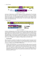
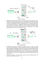
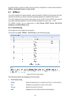
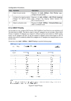
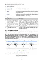
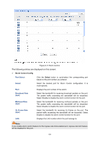
The following entries are displayed on this screen: Priority and CoS-mapping Config Tag-id/Cos-id: Queue TC-id: Indicates the precedence level defined by IEEE802.1P and the CoS ID. Indicates the priority level of egress queue the packets with tag and CoS-id are mapped to. The priority levels of egress queue are labeled as TC0, TC1, TC2 and TC3. Configuration Procedure: Step Operation Description 1 Configure the mapping Required. On QoS→DiffServ→802.1P/CoS mapping relation between the 802.1P page, configure the mapping relation between the priority Tag/CoS and the TC 802.1P priority Tag/CoS and the TC. 2 Select a schedule mode Required. On QoS→DiffServ→Schedule Mode page, select a schedule mode. 9.1.4 Schedule Mode On this page you can select a schedule mode for the switch. When the network is congested, the problem that many packets complete for resources must be solved, usually in the way of queue scheduling. The switch will control the forwarding sequence of the packets according to the priority queues and scheduling algorithms you set. On this switch, the priority levels of egress queue are labeled as TC0, TC1... TC3. Choose the menu QoS→DiffServ→Schedule Mode to load the following page. Figure 9-9 Schedule Mode The following entries are displayed on this screen: Schedule Mode Config SP-Mode: Strict-Priority Mode. In this mode, the queue with higher priority will occupy the whole bandwidth. Packets in the queue with lower priority are sent only when the queue with higher priority is empty. WRR-Mode: Weight Round Robin Mode. In this mode, packets in all the queues are sent in order based on the weight value for each queue. The weight value ratio of TC0, TC1, TC2 and TC3 is 1:2:4:8. 106
-
 1
1 -
2
-
3
-
4
-
5
-
6
-
7
-
8
-
9
-
10
-
11
-
12
-
13
-
14
-
15
-
16
-
17
-
18
-
19
-
20
-
21
-
22
-
23
-
24
-
25
-
26
-
27
-
28
-
29
-
30
-
31
-
32
-
33
-
34
-
35
-
36
-
37
-
38
-
39
-
40
-
41
-
42
-
43
-
44
-
45
-
46
-
47
-
48
-
49
-
50
-
51
-
52
-
53
-
54
-
55
-
56
-
57
-
58
-
59
-
60
-
61
-
62
-
63
-
64
-
65
-
66
-
67
-
68
-
69
-
70
-
71
-
72
-
73
-
74
-
75
-
76
-
77
-
78
-
79
-
80
-
81
-
82
-
83
-
84
-
85
-
86
-
87
-
88
-
89
-
90
-
91
-
92
-
93
-
94
-
95
-
96
-
97
-
98
-
99
-
100
-
101
-
102
-
103
-
104
-
105
-
106
-
107
-
108
-
 109
109 -
 110
110 -
 111
111 -
 112
112 -
 113
113 -
 114
114 -
 115
115 -
 116
116 -
 117
117 -
 118
118 -
 119
119 -
120
-
121
-
122
-
123
-
124
-
125
-
126
-
127
-
128
-
129
-
130
-
131
-
132
-
133
-
134
-
135
-
136
-
137
-
138
-
139
-
140
-
141
-
142
-
143
-
144
-
145
-
146
-
147
-
148
-
149
-
150
-
151
-
152
-
153
-
154
-
155
-
156
-
157
-
158
-
159
-
160
-
161
-
162
-
163
-
164
-
165
-
166
-
167
-
168
-
169
-
170
-
171
-
172
-
173
-
174
-
175
-
176
 |
 |
