TP-Link TL-SG2424P TL-SG2424P V1 User Guide 1910010774 - Page 163
Log Table
 |
View all TP-Link TL-SG2424P manuals
Add to My Manuals
Save this manual to your list of manuals |
Page 163 highlights
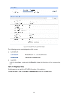
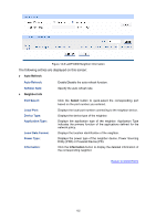
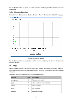
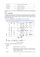
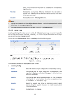
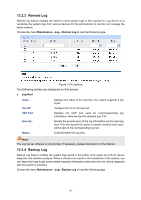
notifications 5 Normal but significant conditions informational 6 Informational messages debugging 7 Debug-level messages Table 13-1 Log Level The Log function is implemented on the Log Table, Local Log, Remote Log and Backup Log pages. 13.2.1 Log Table The switch supports logs output to two directions, namely, log buffer and log file. The information in log buffer will be lost after the switch is rebooted or powered off whereas the information in log file will be kept effective even the switch is rebooted or powered off. Log Table displays the system log information in log buffer. Choose the menu Maintenance→Log→Log Table to load the following page. Figure 13-3 Log Table The following entries are displayed on this screen: Log Info Index: Displays the index of the log information. Time: Displays the time when the log event occurs. The log can get the correct time after you configure on the System->System Info->System Time Web management page. Module: Displays the module which the log information belongs to. You can 155
-
 1
1 -
2
-
3
-
4
-
5
-
6
-
7
-
8
-
9
-
10
-
11
-
12
-
13
-
14
-
15
-
16
-
17
-
18
-
19
-
20
-
21
-
22
-
23
-
24
-
25
-
26
-
27
-
28
-
29
-
30
-
31
-
32
-
33
-
34
-
35
-
36
-
37
-
38
-
39
-
40
-
41
-
42
-
43
-
44
-
45
-
46
-
47
-
48
-
49
-
50
-
51
-
52
-
53
-
54
-
55
-
56
-
57
-
58
-
59
-
60
-
61
-
62
-
63
-
64
-
65
-
66
-
67
-
68
-
69
-
70
-
71
-
72
-
73
-
74
-
75
-
76
-
77
-
78
-
79
-
80
-
81
-
82
-
83
-
84
-
85
-
86
-
87
-
88
-
89
-
90
-
91
-
92
-
93
-
94
-
95
-
96
-
97
-
98
-
99
-
100
-
101
-
102
-
103
-
104
-
105
-
106
-
107
-
108
-
109
-
110
-
111
-
112
-
113
-
114
-
115
-
116
-
117
-
118
-
119
-
120
-
121
-
122
-
123
-
124
-
125
-
126
-
127
-
128
-
129
-
130
-
131
-
132
-
133
-
134
-
135
-
136
-
137
-
138
-
139
-
140
-
141
-
142
-
143
-
144
-
145
-
146
-
147
-
148
-
149
-
150
-
151
-
152
-
153
-
154
-
155
-
156
-
157
-
 158
158 -
 159
159 -
 160
160 -
 161
161 -
 162
162 -
 163
163 -
 164
164 -
 165
165 -
 166
166 -
 167
167 -
 168
168 -
169
-
170
-
171
-
172
-
173
-
174
-
175
-
176
 |
 |