TP-Link TL-SG2424P TL-SG2424P V1 User Guide 1910010774 - Page 87
TC Protect
 |
View all TP-Link TL-SG2424P manuals
Add to My Manuals
Save this manual to your list of manuals |
Page 87 highlights
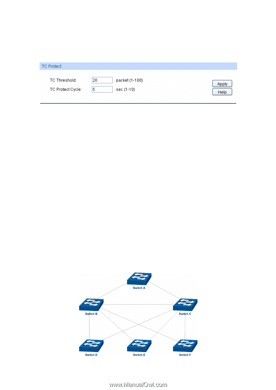
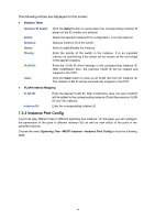
7.4.2 TC Protect When TC Protect is enabled for the port on Port Protect page, the TC threshold and TC protect cycle need to be configured on this page. Choose the menu Spanning Tree→STP Security→TC Protect to load the following page. Figure 7-11 TC Protect The following entries are displayed on this screen: TC Protect TC Threshold: Enter a number from 1 to 100. It is the maximum number of the TC-BPDUs received by the switch in a TC Protect Cycle. The default value is 20. TC Protect Cycle: Enter a value from 1 to 10 to specify the TC Protect Cycle. The default value is 5. 7.5 Application Example for STP Function Network Requirements Switch A, B, C, D and E all support MSTP function. A is the central switch. B and C are switches in the convergence layer. D, E and F are switches in the access layer. There are 6 VLANs labeled as VLAN101-VLAN106 in the network. All switches run MSTP and belong to the same MST region. The data in VLAN101, 103 and 105 are transmitted in the STP with B as the root bridge. The data in VLAN102, 104 and 106 are transmitted in the STP with C as the root bridge. Network Diagram 79
-
 1
1 -
2
-
3
-
4
-
5
-
6
-
7
-
8
-
9
-
10
-
11
-
12
-
13
-
14
-
15
-
16
-
17
-
18
-
19
-
20
-
21
-
22
-
23
-
24
-
25
-
26
-
27
-
28
-
29
-
30
-
31
-
32
-
33
-
34
-
35
-
36
-
37
-
38
-
39
-
40
-
41
-
42
-
43
-
44
-
45
-
46
-
47
-
48
-
49
-
50
-
51
-
52
-
53
-
54
-
55
-
56
-
57
-
58
-
59
-
60
-
61
-
62
-
63
-
64
-
65
-
66
-
67
-
68
-
69
-
70
-
71
-
72
-
73
-
74
-
75
-
76
-
77
-
78
-
79
-
80
-
81
-
 82
82 -
 83
83 -
 84
84 -
 85
85 -
 86
86 -
 87
87 -
 88
88 -
 89
89 -
 90
90 -
 91
91 -
 92
92 -
93
-
94
-
95
-
96
-
97
-
98
-
99
-
100
-
101
-
102
-
103
-
104
-
105
-
106
-
107
-
108
-
109
-
110
-
111
-
112
-
113
-
114
-
115
-
116
-
117
-
118
-
119
-
120
-
121
-
122
-
123
-
124
-
125
-
126
-
127
-
128
-
129
-
130
-
131
-
132
-
133
-
134
-
135
-
136
-
137
-
138
-
139
-
140
-
141
-
142
-
143
-
144
-
145
-
146
-
147
-
148
-
149
-
150
-
151
-
152
-
153
-
154
-
155
-
156
-
157
-
158
-
159
-
160
-
161
-
162
-
163
-
164
-
165
-
166
-
167
-
168
-
169
-
170
-
171
-
172
-
173
-
174
-
175
-
176
 |
 |