TP-Link TL-SG2424P TL-SG2424P V1 User Guide 1910010774 - Page 101
Multicast IP
 |
View all TP-Link TL-SG2424P manuals
Add to My Manuals
Save this manual to your list of manuals |
Page 101 highlights
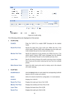
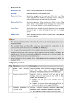
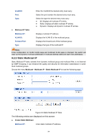
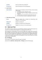
2 Configure ports On VLAN→802.1Q VLAN function pages. For port 3, configure its link type as GENERAL and its egress rule as TAG, and add it to VLAN3, VLAN4 and VLAN5. For port 4, configure its link type as GENERAL and its egress rule as UNTAG, and add it to VLAN3 and VLAN 4. For port 5, configure its link type as GENERAL and its egress rule as UNTAG, and add it to VLAN3 and VLAN 5. 3 Enable IGMP Enable IGMP Snooping function globally on Multicast→IGMP Snooping function Snooping→Snooping Config page. Enable IGMP Snooping function for port3, port4 and port 5 on Multicast→IGMP Snooping→Port Config page. 4 Enable Multicast Enable Multicast VLAN, configure the VLAN ID of a multicast VLAN VLAN as 3 and keep the other parameters as default on Multicast→IGMP Snooping→Multicast VLAN page. 5 Check VLAN Multicast 3-5 and Multicast VLAN 3 will be displayed in the IGMP Snooping Status table on the Multicast→IGMP Snooping→ Snooping Config page. 8.2 Multicast IP In a network, receivers can join different multicast groups appropriate to their needs. The switch forwards multicast streams based on multicast address table. The Multicast IP can be implemented on Multicast IP Table and Static Multicast IP page. 8.2.1 Multicast IP Table On this page you can view the multicast IP table on the switch. Choose the menu Multicast→Multicast IP→Multicast IP Table to load the following page. Figure 8-8 Multicast IP Table The following entries are displayed on this screen: Search Option Multicast IP: Enter the multicast IP address the desired entry must carry. 93
-
 1
1 -
2
-
3
-
4
-
5
-
6
-
7
-
8
-
9
-
10
-
11
-
12
-
13
-
14
-
15
-
16
-
17
-
18
-
19
-
20
-
21
-
22
-
23
-
24
-
25
-
26
-
27
-
28
-
29
-
30
-
31
-
32
-
33
-
34
-
35
-
36
-
37
-
38
-
39
-
40
-
41
-
42
-
43
-
44
-
45
-
46
-
47
-
48
-
49
-
50
-
51
-
52
-
53
-
54
-
55
-
56
-
57
-
58
-
59
-
60
-
61
-
62
-
63
-
64
-
65
-
66
-
67
-
68
-
69
-
70
-
71
-
72
-
73
-
74
-
75
-
76
-
77
-
78
-
79
-
80
-
81
-
82
-
83
-
84
-
85
-
86
-
87
-
88
-
89
-
90
-
91
-
92
-
93
-
94
-
95
-
 96
96 -
 97
97 -
 98
98 -
 99
99 -
 100
100 -
 101
101 -
 102
102 -
 103
103 -
 104
104 -
 105
105 -
 106
106 -
107
-
108
-
109
-
110
-
111
-
112
-
113
-
114
-
115
-
116
-
117
-
118
-
119
-
120
-
121
-
122
-
123
-
124
-
125
-
126
-
127
-
128
-
129
-
130
-
131
-
132
-
133
-
134
-
135
-
136
-
137
-
138
-
139
-
140
-
141
-
142
-
143
-
144
-
145
-
146
-
147
-
148
-
149
-
150
-
151
-
152
-
153
-
154
-
155
-
156
-
157
-
158
-
159
-
160
-
161
-
162
-
163
-
164
-
165
-
166
-
167
-
168
-
169
-
170
-
171
-
172
-
173
-
174
-
175
-
176
 |
 |