TP-Link TL-SG2424P TL-SG2424P V1 User Guide 1910010774 - Page 14
Appearance Description
 |
View all TP-Link TL-SG2424P manuals
Add to My Manuals
Save this manual to your list of manuals |
Page 14 highlights
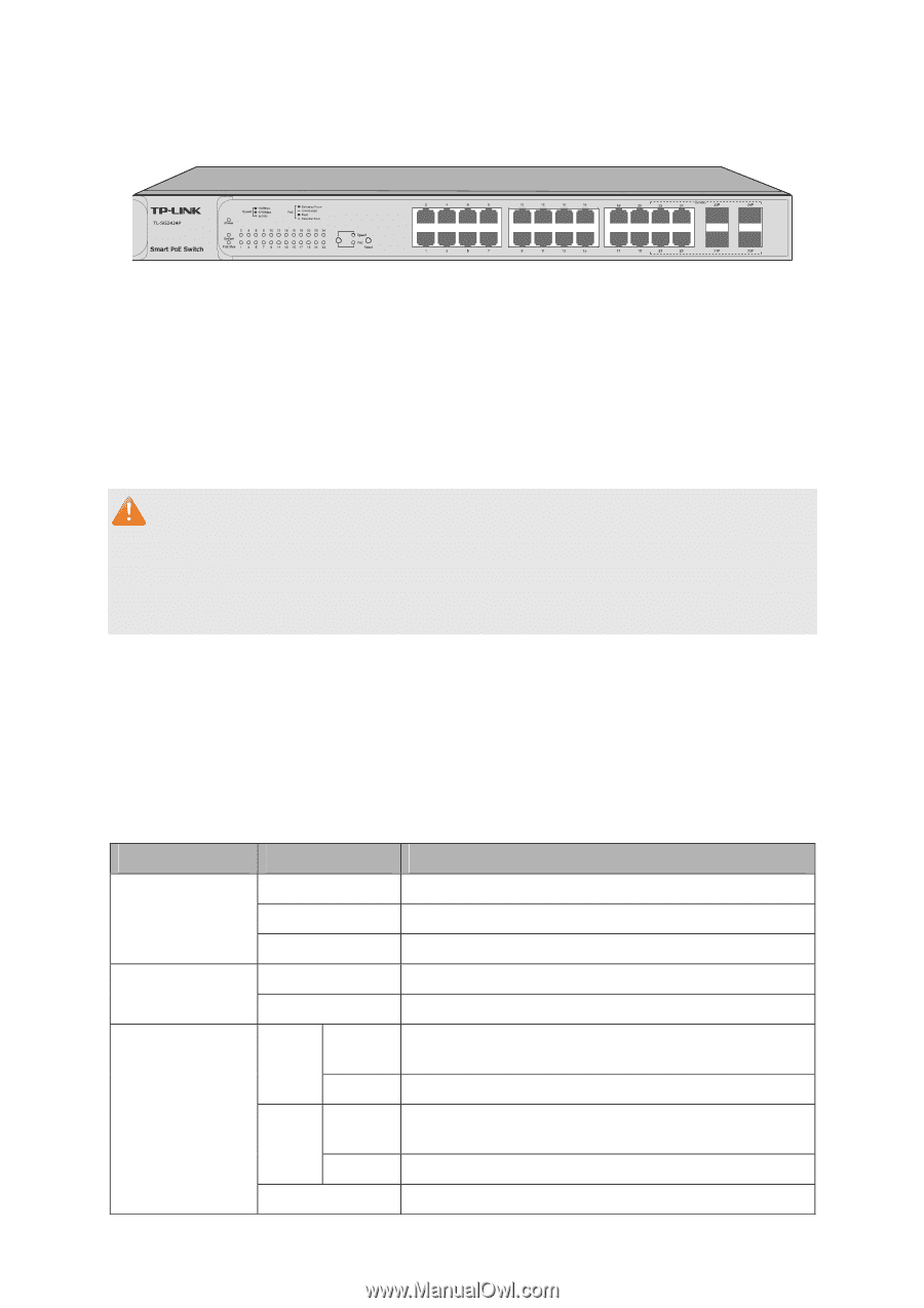
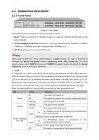
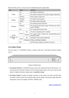
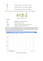
2.3 Appearance Description 2.3.1 Front Panel Figure 2-1 Front Panel The following parts are located on the front panel of the switch: Reset: Press this button for 5 seconds or above to reset the software settings back to the factory defaults. 10/100/1000Mbps RJ45 Ports: Designed to connect to the device with a bandwidth of 10Mbps, 100Mbps or 1000Mbps. Each has a corresponding 1000Mbps LED. SFP Ports: Designed to install the SFP module. Note: When using the SFP port with a 100M module or a gigabit module, you need to configure its corresponding Speed and Duplex mode on Switching→Port→Port Config page. For 100M module, please select 100MFD while select 1000MFD for gigabit module. By default, the Speed and Duplex mode of SFP port is 1000MFD. LEDs TL-SG2424P has a LED mode switch button which is for switching the LED status indication. When the Speed LED is on, the port LED is indicating the data transmission rate. When the PoE LED is on, the port LED is indicating the power supply status. By default the Speed LED is on. Pressing the mode switch button, the Speed LED will turn off and the PoE LED will light up. Then the PoE LED will turn off after being on for 60 seconds and the Speed LED will light up again. When the Speed LED is on, the port LED is indicating the data transmission rate. LED Status Indication On The switch is powered on. Power Off The switch is powered off or power supply is abnormal. Flashing Power supply is abnormal. System Flashing On/Off The switch works properly. The switch works improperly. 10/100/1000Mbps Port LED Green Yellow On Flashing On Flashing A 1000Mbps device is connected to the corresponding port, but no activity. Data is being transmitted or received. A 10/100Mbps device is connected to the corresponding port, but no activity. Data is being transmitted or received. Off No device is connected to the corresponding port. 6
-
 1
1 -
2
-
3
-
4
-
5
-
6
-
7
-
8
-
 9
9 -
 10
10 -
 11
11 -
 12
12 -
 13
13 -
 14
14 -
 15
15 -
 16
16 -
 17
17 -
 18
18 -
 19
19 -
20
-
21
-
22
-
23
-
24
-
25
-
26
-
27
-
28
-
29
-
30
-
31
-
32
-
33
-
34
-
35
-
36
-
37
-
38
-
39
-
40
-
41
-
42
-
43
-
44
-
45
-
46
-
47
-
48
-
49
-
50
-
51
-
52
-
53
-
54
-
55
-
56
-
57
-
58
-
59
-
60
-
61
-
62
-
63
-
64
-
65
-
66
-
67
-
68
-
69
-
70
-
71
-
72
-
73
-
74
-
75
-
76
-
77
-
78
-
79
-
80
-
81
-
82
-
83
-
84
-
85
-
86
-
87
-
88
-
89
-
90
-
91
-
92
-
93
-
94
-
95
-
96
-
97
-
98
-
99
-
100
-
101
-
102
-
103
-
104
-
105
-
106
-
107
-
108
-
109
-
110
-
111
-
112
-
113
-
114
-
115
-
116
-
117
-
118
-
119
-
120
-
121
-
122
-
123
-
124
-
125
-
126
-
127
-
128
-
129
-
130
-
131
-
132
-
133
-
134
-
135
-
136
-
137
-
138
-
139
-
140
-
141
-
142
-
143
-
144
-
145
-
146
-
147
-
148
-
149
-
150
-
151
-
152
-
153
-
154
-
155
-
156
-
157
-
158
-
159
-
160
-
161
-
162
-
163
-
164
-
165
-
166
-
167
-
168
-
169
-
170
-
171
-
172
-
173
-
174
-
175
-
176
 |
 |