TP-Link TL-SG2424P TL-SG2424P V1 User Guide 1910010774 - Page 89
Port Config
 |
View all TP-Link TL-SG2424P manuals
Add to My Manuals
Save this manual to your list of manuals |
Page 89 highlights
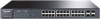
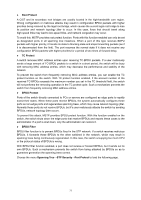
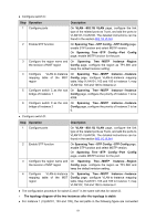
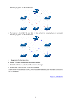
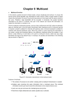
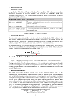
Configure switch C: Step Operation Description 1 Configure ports On VLAN→802.1Q VLAN page, configure the link type of the related ports as Trunk, and add the ports to VLAN101-VLAN106. The detailed instructions can be found in the section 802.1Q VLAN. 2 Enable STP function On Spanning Tree→STP Config→STP Config page, enable STP function and select MSTP version. On Spanning Tree→STP Config→Port Config page, enable MSTP function for the port. 3 Configure the region name and On Spanning Tree→MSTP Instance→Region the revision of MST region Config page, configure the region as TP-LINK and keep the default revision setting. 4 Configure VLAN-to-Instance On Spanning Tree→MSTP Instance→Instance mapping table of the MST Config page, configure VLAN-to-Instance mapping region table. Map VLAN101, 103 and 105 to Instance 1; map VLAN102, 104 and 106 to Instance 2. 5 Configure switch C as the root On Spanning Tree→MSTP Instance→Instance bridge of Instance 1 Config page, configure the priority of Instance 1 to be 4096. 6 Configure switch C as the root On Spanning Tree→MSTP Instance→Instance bridge of Instance 2 Config page, configure the priority of Instance 2 to be 0. Configure switch D: Step Operation Description 1 Configure ports On VLAN→802.1Q VLAN page, configure the link type of the related ports as Trunk, and add the ports to VLAN101-VLAN106. The detailed instructions can be found in the section 802.1Q VLAN. 2 Enable STP function On Spanning Tree→STP Config→STP Config page, enable STP function and select MSTP version. On Spanning Tree→STP Config→Port Config page, enable MSTP function for the port. 3 Configure the region name and On Spanning Tree→MSTP Instance→Region the revision of MST region Config page, configure the region as TP-LINK and keep the default revision setting. 4 Configure VLAN-to-Instance On Spanning Tree→MSTP Instance→Instance mapping table of the MST Config page, configure VLAN-to-Instance mapping region table. Map VLAN101, 103 and 105 to Instance 1; map VLAN102, 104 and 106 to Instance 2. The configuration procedure for switch E and F is the same with that for switch D. The topology diagram of the two instances after the topology is stable For Instance 1 (VLAN101, 103 and 105), the red paths in the following figure are connected 81
-
 1
1 -
2
-
3
-
4
-
5
-
6
-
7
-
8
-
9
-
10
-
11
-
12
-
13
-
14
-
15
-
16
-
17
-
18
-
19
-
20
-
21
-
22
-
23
-
24
-
25
-
26
-
27
-
28
-
29
-
30
-
31
-
32
-
33
-
34
-
35
-
36
-
37
-
38
-
39
-
40
-
41
-
42
-
43
-
44
-
45
-
46
-
47
-
48
-
49
-
50
-
51
-
52
-
53
-
54
-
55
-
56
-
57
-
58
-
59
-
60
-
61
-
62
-
63
-
64
-
65
-
66
-
67
-
68
-
69
-
70
-
71
-
72
-
73
-
74
-
75
-
76
-
77
-
78
-
79
-
80
-
81
-
82
-
83
-
 84
84 -
 85
85 -
 86
86 -
 87
87 -
 88
88 -
 89
89 -
 90
90 -
 91
91 -
 92
92 -
 93
93 -
 94
94 -
95
-
96
-
97
-
98
-
99
-
100
-
101
-
102
-
103
-
104
-
105
-
106
-
107
-
108
-
109
-
110
-
111
-
112
-
113
-
114
-
115
-
116
-
117
-
118
-
119
-
120
-
121
-
122
-
123
-
124
-
125
-
126
-
127
-
128
-
129
-
130
-
131
-
132
-
133
-
134
-
135
-
136
-
137
-
138
-
139
-
140
-
141
-
142
-
143
-
144
-
145
-
146
-
147
-
148
-
149
-
150
-
151
-
152
-
153
-
154
-
155
-
156
-
157
-
158
-
159
-
160
-
161
-
162
-
163
-
164
-
165
-
166
-
167
-
168
-
169
-
170
-
171
-
172
-
173
-
174
-
175
-
176
 |
 |