TP-Link TL-SG2424P TL-SG2424P V1 User Guide 1910010774 - Page 75
Port States, Port Roles
 |
View all TP-Link TL-SG2424P manuals
Add to My Manuals
Save this manual to your list of manuals |
Page 75 highlights
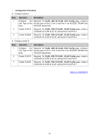
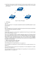
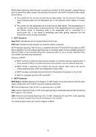
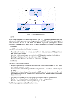
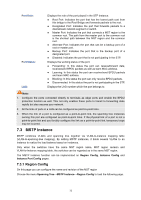
Figure 7-2 Basic MSTP diagram MSTP MSTP divides a network into several MST regions. The CST is generated between these MST regions, and multiple spanning trees can be generated in each MST region. Each spanning tree is called an instance. As well as STP, MSTP uses BPDUs to generate spanning tree. The only difference is that the BPDU for MSTP carries the MSTP configuration information on the switches. Port States In an MSTP, ports can be in the following four states: Forwarding: In this status the port can receive/forward data, receive/send BPDU packets as well as learn MAC address. Learning: In this status the port can receive/send BPDU packets and learn MAC address. Blocking: In this status the port can only receive BPDU packets. Disconnected: In this status the port is not participating in the STP. Port Roles In an MSTP, the following roles exist: Root Port: Indicates the port that has the lowest path cost from this bridge to the Root Bridge and forwards packets to the root. Designated Port: Indicates the port that forwards packets to a downstream network segment or switch. Master Port: Indicates the port that connects a MST region to the common root. The path from the master port to the common root is the shortest path between this MST region and the common root. Alternate Port: Indicates the port that can be a backup port of a root or master port. Backup Port: Indicates the port that is the backup port of a designated port. Disabled: Indicates the port that is not participating in the STP. The following diagram shows the different port roles. 67
-
 1
1 -
2
-
3
-
4
-
5
-
6
-
7
-
8
-
9
-
10
-
11
-
12
-
13
-
14
-
15
-
16
-
17
-
18
-
19
-
20
-
21
-
22
-
23
-
24
-
25
-
26
-
27
-
28
-
29
-
30
-
31
-
32
-
33
-
34
-
35
-
36
-
37
-
38
-
39
-
40
-
41
-
42
-
43
-
44
-
45
-
46
-
47
-
48
-
49
-
50
-
51
-
52
-
53
-
54
-
55
-
56
-
57
-
58
-
59
-
60
-
61
-
62
-
63
-
64
-
65
-
66
-
67
-
68
-
69
-
 70
70 -
 71
71 -
 72
72 -
 73
73 -
 74
74 -
 75
75 -
 76
76 -
 77
77 -
 78
78 -
 79
79 -
 80
80 -
81
-
82
-
83
-
84
-
85
-
86
-
87
-
88
-
89
-
90
-
91
-
92
-
93
-
94
-
95
-
96
-
97
-
98
-
99
-
100
-
101
-
102
-
103
-
104
-
105
-
106
-
107
-
108
-
109
-
110
-
111
-
112
-
113
-
114
-
115
-
116
-
117
-
118
-
119
-
120
-
121
-
122
-
123
-
124
-
125
-
126
-
127
-
128
-
129
-
130
-
131
-
132
-
133
-
134
-
135
-
136
-
137
-
138
-
139
-
140
-
141
-
142
-
143
-
144
-
145
-
146
-
147
-
148
-
149
-
150
-
151
-
152
-
153
-
154
-
155
-
156
-
157
-
158
-
159
-
160
-
161
-
162
-
163
-
164
-
165
-
166
-
167
-
168
-
169
-
170
-
171
-
172
-
173
-
174
-
175
-
176
 |
 |
