ZyXEL P-2602HW-D3A User Guide - Page 317
P-2602HWL-DxA Series User's Guide, Diagnostic, Diagnostic: DSL Line continued
 |
View all ZyXEL P-2602HW-D3A manuals
Add to My Manuals
Save this manual to your list of manuals |
Page 317 highlights
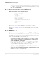
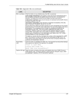
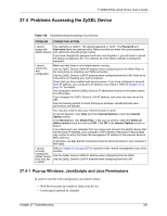
P-2602H(W)(L)-DxA Series User's Guide Table 124 Diagnostic: DSL Line (continued) LABEL DESCRIPTION DSL Line Status Click this button to view statistics about the DSL connections. noise margin downstream is the signal to noise ratio for the downstream part of the connection (coming into the ZyXEL Device from the ISP). It is measured in decibels. The higher the number the more signal and less noise there is. output power upstream is the amount of power (in decibels) that the ZyXEL Device is using to transmit to the ISP. attentuation downstream is the reduction in amplitude (in decibels) of the DSL signal coming into the ZyXEL Device from the ISP. Discrete Multi-Tone (DMT) modulation divides up a line's bandwidth into sub-carriers (sub-channels) of 4.3125 KHz each called tones. The rest of the display is the line's bit allocation. This is displayed as the number (in hexadecimal format) of bits transmitted for each tone. This can be used to determine the quality of the connection, whether a given sub-carrier loop has sufficient margins to support certain ADSL transmission rates, and possibly to determine whether particular specific types of interference or line attenuation exist. Refer to the ITU-T G.992.1 recommendation for more information on DMT. The better (or shorter) the line, the higher the number of bits transmitted for a DMT tone. The maximum number of bits that can be transmitted per DMT tone is 15. There will be some tones without any bits as there has to be space between the upstream and downstream channels. Reset ADSL Line Click this button to reinitialize the ADSL line. The large text box above then displays the progress and results of this operation, for example: "Start to reset ADSL Loading ADSL modem F/W... Reset ADSL Line Successfully!" Capture All Logs Click this button to display information and statistics about your ZyXEL Device's ATM statistics, DSL connection statistics, DHCP settings, firmware version, WAN and gateway IP address, VPI/VCI and LAN IP address. Chapter 26 Diagnostic 317
-
 1
1 -
2
-
3
-
4
-
5
-
6
-
7
-
8
-
9
-
10
-
11
-
12
-
13
-
14
-
15
-
16
-
17
-
18
-
19
-
20
-
21
-
22
-
23
-
24
-
25
-
26
-
27
-
28
-
29
-
30
-
31
-
32
-
33
-
34
-
35
-
36
-
37
-
38
-
39
-
40
-
41
-
42
-
43
-
44
-
45
-
46
-
47
-
48
-
49
-
50
-
51
-
52
-
53
-
54
-
55
-
56
-
57
-
58
-
59
-
60
-
61
-
62
-
63
-
64
-
65
-
66
-
67
-
68
-
69
-
70
-
71
-
72
-
73
-
74
-
75
-
76
-
77
-
78
-
79
-
80
-
81
-
82
-
83
-
84
-
85
-
86
-
87
-
88
-
89
-
90
-
91
-
92
-
93
-
94
-
95
-
96
-
97
-
98
-
99
-
100
-
101
-
102
-
103
-
104
-
105
-
106
-
107
-
108
-
109
-
110
-
111
-
112
-
113
-
114
-
115
-
116
-
117
-
118
-
119
-
120
-
121
-
122
-
123
-
124
-
125
-
126
-
127
-
128
-
129
-
130
-
131
-
132
-
133
-
134
-
135
-
136
-
137
-
138
-
139
-
140
-
141
-
142
-
143
-
144
-
145
-
146
-
147
-
148
-
149
-
150
-
151
-
152
-
153
-
154
-
155
-
156
-
157
-
158
-
159
-
160
-
161
-
162
-
163
-
164
-
165
-
166
-
167
-
168
-
169
-
170
-
171
-
172
-
173
-
174
-
175
-
176
-
177
-
178
-
179
-
180
-
181
-
182
-
183
-
184
-
185
-
186
-
187
-
188
-
189
-
190
-
191
-
192
-
193
-
194
-
195
-
196
-
197
-
198
-
199
-
200
-
201
-
202
-
203
-
204
-
205
-
206
-
207
-
208
-
209
-
210
-
211
-
212
-
213
-
214
-
215
-
216
-
217
-
218
-
219
-
220
-
221
-
222
-
223
-
224
-
225
-
226
-
227
-
228
-
229
-
230
-
231
-
232
-
233
-
234
-
235
-
236
-
237
-
238
-
239
-
240
-
241
-
242
-
243
-
244
-
245
-
246
-
247
-
248
-
249
-
250
-
251
-
252
-
253
-
254
-
255
-
256
-
257
-
258
-
259
-
260
-
261
-
262
-
263
-
264
-
265
-
266
-
267
-
268
-
269
-
270
-
271
-
272
-
273
-
274
-
275
-
276
-
277
-
278
-
279
-
280
-
281
-
282
-
283
-
284
-
285
-
286
-
287
-
288
-
289
-
290
-
291
-
292
-
293
-
294
-
295
-
296
-
297
-
298
-
299
-
300
-
301
-
302
-
303
-
304
-
305
-
306
-
307
-
308
-
309
-
310
-
311
-
 312
312 -
 313
313 -
 314
314 -
 315
315 -
 316
316 -
 317
317 -
 318
318 -
 319
319 -
 320
320 -
 321
321 -
 322
322 -
323
-
324
-
325
-
326
-
327
-
328
-
329
-
330
-
331
-
332
-
333
-
334
-
335
-
336
-
337
-
338
-
339
-
340
-
341
-
342
-
343
-
344
-
345
-
346
-
347
-
348
-
349
-
350
-
351
-
352
-
353
-
354
-
355
-
356
-
357
-
358
-
359
-
360
-
361
-
362
-
363
-
364
-
365
-
366
-
367
-
368
-
369
-
370
-
371
-
372
-
373
-
374
-
375
-
376
-
377
-
378
-
379
-
380
-
381
-
382
-
383
-
384
-
385
-
386
-
387
-
388
-
389
-
390
-
391
-
392
-
393
-
394
-
395
-
396
-
397
-
398
-
399
-
400
-
401
-
402
-
403
-
404
-
405
-
406
-
407
-
408
-
409
-
410
-
411
-
412
-
413
-
414
-
415
-
416
-
417
-
418
-
419
-
420
-
421
-
422
-
423
-
424
-
425
-
426
-
427
 |
 |