Dell OptiPlex Gn Reference and Installation Guide (.pdf) - Page 23
Security Cable Slot and Padlock Ring, Attaching the Optional Floor, Stand
 |
View all Dell OptiPlex Gn manuals
Add to My Manuals
Save this manual to your list of manuals |
Page 23 highlights
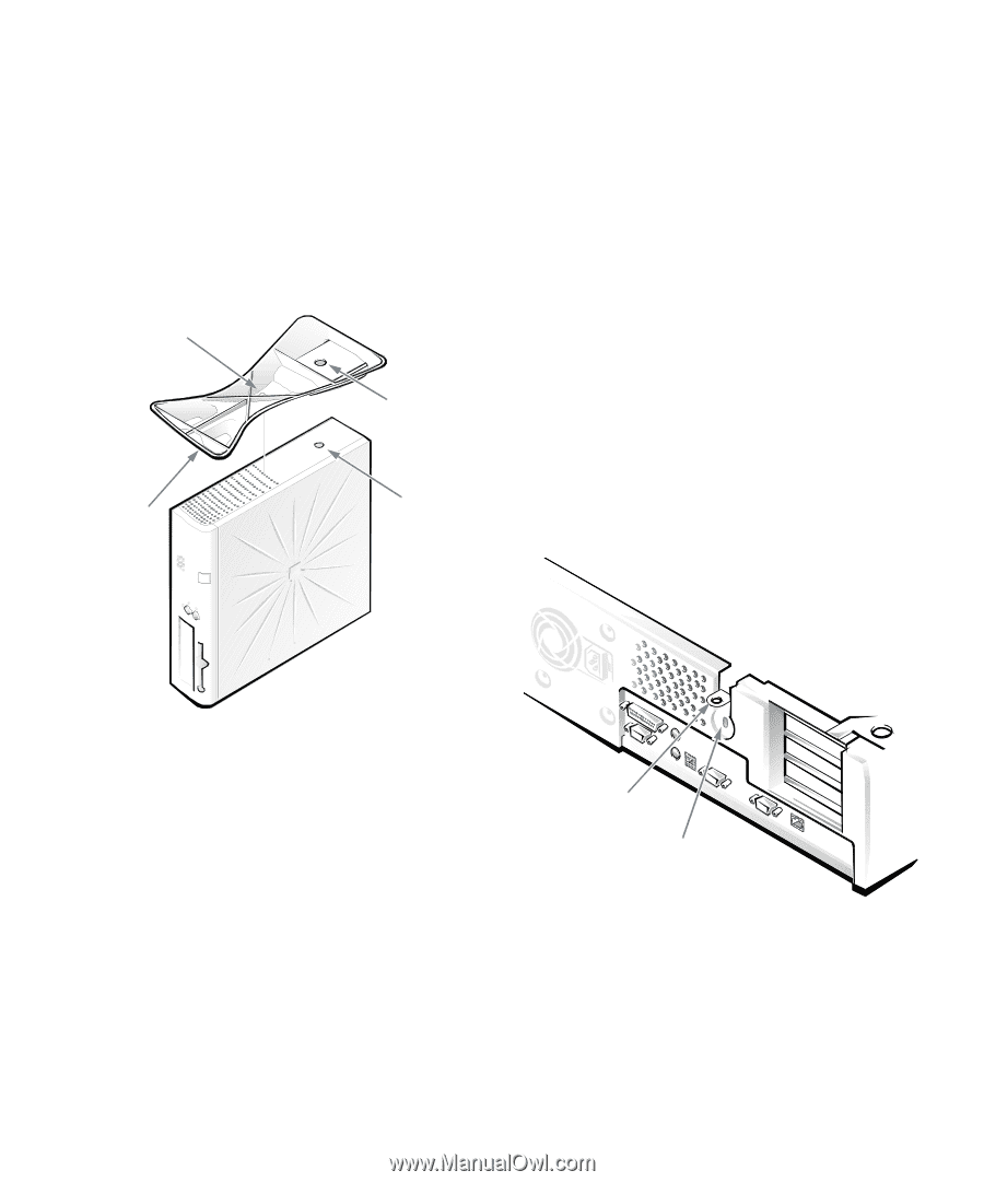
Attach the floor stand as follows: 1. Turn the computer onto its right side, so that the drive bays are at the bottom. 2. Fit the floor stand onto what was the left side of the computer. Position the floor stand as shown in Figure 1-2. Align the large round locator hole in the floor stand with the securing button on the side of the cover, and align the captive thumbscrew in the stand with the screw hole in the cover. captive screw locator hole locator pin (on underside of floor stand) securing button Security Cable Slot and Padlock Ring On the back of the computer are a security cable slot and padlock ring (see Figure 1-3) for attaching commercially available antitheft devices. Antitheft devices for personal computers usually include a segment of galvanized cable with an attached locking device and key. To prevent unauthorized removal of your computer, loop the cable around an immovable object, insert the locking device into the security cable slot on the back of your computer, and lock the device with the key provided. Complete instructions for installing this kind of antitheft device are usually included with the device. NOTE: Antitheft devices are of differing designs. Before purchasing such a device, make sure it will work with the cable slot on your computer. The padlock ring allows you to secure the computer cover to the chassis to prevent unauthorized internal access. To use the padlock ring, insert a commercially available padlock through the ring and lock the padlock. Figure 1-2. Attaching the Optional Floor Stand As you lower the stand into place, make sure the locator pin (see Figure 1-2) heads into the corner hole of the hole pattern as shown. When the stand is in place, tighten the thumbscrew. 3. Rotate the computer so that the floor stand is at the bottom and the drives are at the top. To remove the floor stand, turn the computer over so that the floor stand is at the top, loosen the screw and lift the floor stand away, and place the computer in a horizontal position. padlock ring security cable slot Figure 1-3. Security Cable Slot and Padlock Ring Introduction 1-5
-
 1
1 -
2
-
3
-
4
-
5
-
6
-
7
-
8
-
9
-
10
-
11
-
12
-
13
-
14
-
15
-
16
-
17
-
 18
18 -
 19
19 -
 20
20 -
 21
21 -
 22
22 -
 23
23 -
 24
24 -
 25
25 -
 26
26 -
 27
27 -
 28
28 -
29
-
30
-
31
-
32
-
33
-
34
-
35
-
36
-
37
-
38
-
39
-
40
-
41
-
42
-
43
-
44
-
45
-
46
-
47
-
48
-
49
-
50
-
51
-
52
-
53
-
54
-
55
-
56
-
57
-
58
-
59
-
60
-
61
-
62
-
63
-
64
-
65
-
66
-
67
-
68
-
69
-
70
-
71
-
72
-
73
-
74
-
75
-
76
-
77
-
78
-
79
-
80
-
81
-
82
-
83
-
84
-
85
-
86
-
87
-
88
-
89
-
90
-
91
-
92
-
93
-
94
-
95
-
96
-
97
-
98
-
99
-
100
-
101
-
102
-
103
-
104
-
105
-
106
-
107
-
108
-
109
-
110
-
111
-
112
-
113
-
114
-
115
-
116
-
117
-
118
-
119
-
120
-
121
-
122
-
123
-
124
-
125
-
126
 |
 |