Dell OptiPlex Gn Reference and Installation Guide (.pdf) - Page 83
Installing a Drive in the 5.25-Inch, Drive Bracket, Inserting the Drive Bracket into
 |
View all Dell OptiPlex Gn manuals
Add to My Manuals
Save this manual to your list of manuals |
Page 83 highlights
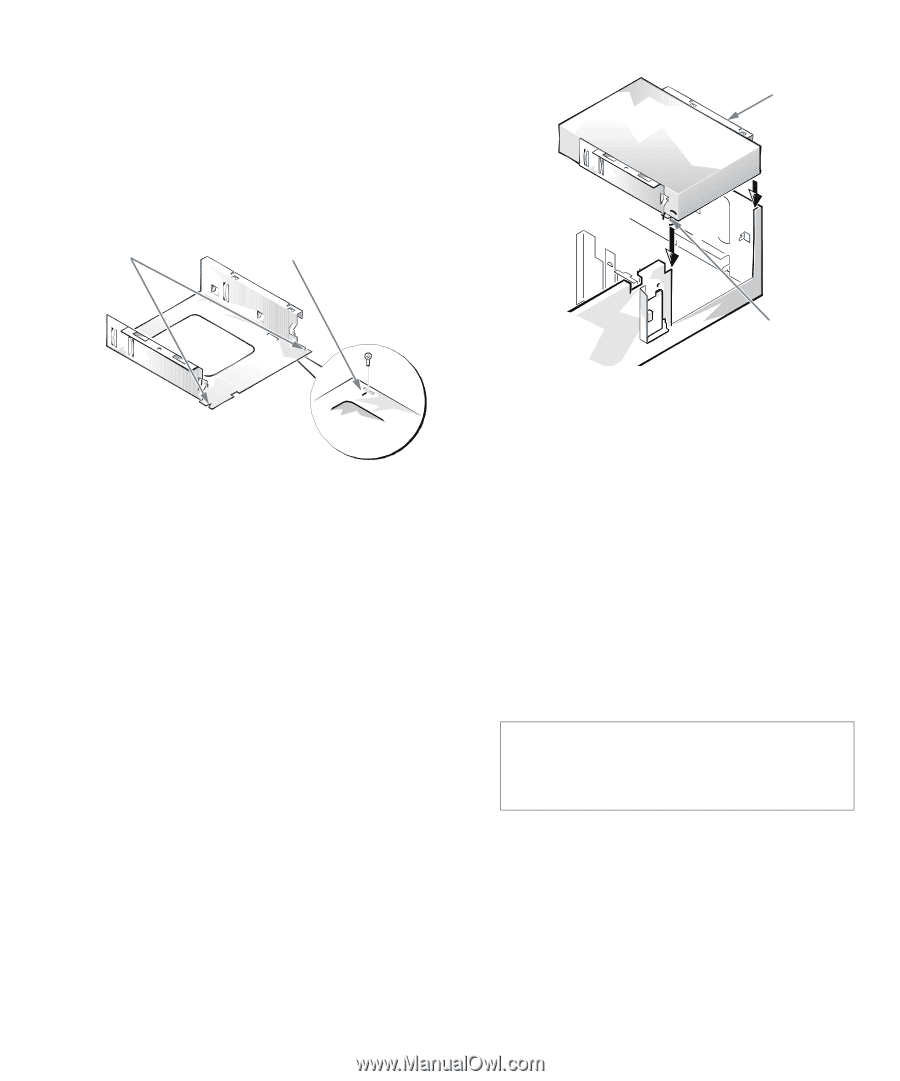
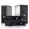
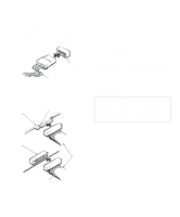
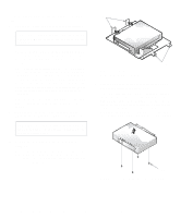
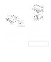
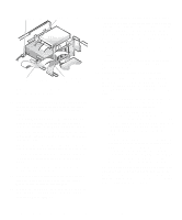
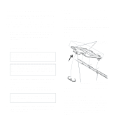
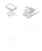
5. Attach the bracket to the new drive. Turn the drive upside down, and locate the four screw holes around its perimeter. Fit the bracket over the drive so that the notched end aligns with the front of the drive. Use the score marks on the drive bracket to help align the screw holes on the drive with the screw holes on the bracket (see Figure 7-8). notches score mark bracket notches Figure 7-8. Installing a Drive in the 5.25-Inch Drive Bracket To further ensure proper positioning of the drive in the chassis, insert and tighten all four screws in the order in which the holes are numbered (the holes are marked "1" through "4"). 6. Reinstall the 5.25-inch drive/bracket assembly in the chassis. Align the notches on the front of the drive bracket (see Figure 7-8) with the front of the computer. Hold the bracket level, and lower the assembly straight down into place (see Figure 7-9). Figure 7-9. Inserting the Drive Bracket into the Drive Bay 7. If you are installing a drive that has its own controller card, install the controller card in an expansion slot. See "Installing an Expansion Card" in Chapter 6. 8. Connect a DC power cable to the power input connector on the back of the drive (see Figure 7-10). 9. Connect the appropriate interface cable to the interface connector on the back of the drive (see Figure 7-10). Match the colored strip on the interface cable to the pin-1 end of the connector on the drive. CAUTION: You must match the colored strip on the cable with pin 1 on the drive's interface connector to avoid possible damage to your system. Installing Drives 7-5
-
 1
1 -
2
-
3
-
4
-
5
-
6
-
7
-
8
-
9
-
10
-
11
-
12
-
13
-
14
-
15
-
16
-
17
-
18
-
19
-
20
-
21
-
22
-
23
-
24
-
25
-
26
-
27
-
28
-
29
-
30
-
31
-
32
-
33
-
34
-
35
-
36
-
37
-
38
-
39
-
40
-
41
-
42
-
43
-
44
-
45
-
46
-
47
-
48
-
49
-
50
-
51
-
52
-
53
-
54
-
55
-
56
-
57
-
58
-
59
-
60
-
61
-
62
-
63
-
64
-
65
-
66
-
67
-
68
-
69
-
70
-
71
-
72
-
73
-
74
-
75
-
76
-
77
-
 78
78 -
 79
79 -
 80
80 -
 81
81 -
 82
82 -
 83
83 -
 84
84 -
 85
85 -
 86
86 -
 87
87 -
 88
88 -
89
-
90
-
91
-
92
-
93
-
94
-
95
-
96
-
97
-
98
-
99
-
100
-
101
-
102
-
103
-
104
-
105
-
106
-
107
-
108
-
109
-
110
-
111
-
112
-
113
-
114
-
115
-
116
-
117
-
118
-
119
-
120
-
121
-
122
-
123
-
124
-
125
-
126
 |
 |