Dell OptiPlex Gn Reference and Installation Guide (.pdf) - Page 86
Securing the Hard-Disk Drive to, the Bracket, Attaching Hard-Disk Drive, Cables
 |
View all Dell OptiPlex Gn manuals
Add to My Manuals
Save this manual to your list of manuals |
Page 86 highlights
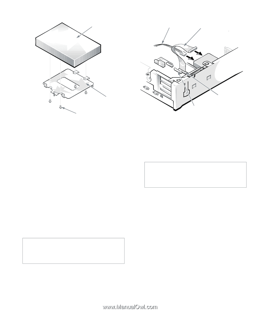
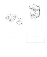
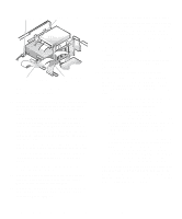
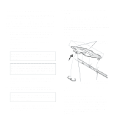
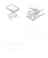
hard-disk drive DC power cable EIDE cable bracket screws (4) Figure 7-12. Securing the Hard-Disk Drive to the Bracket 7. Reinstall the hard-disk drive/bracket assembly in the chassis. Grasp the bracket by the tab containing the captive screw, and hold the bracket at a 45-degree angle to the chassis floor. Align the two tabs on the other side of the bracket with the score marks on the chassis floor. Insert the two tabs into the slots in the chassis floor divider, and rotate the assembly downward. Then tighten the captive screw until the bracket is securely fastened to the chassis floor (see Figure 7-11). 8. Connect one end of the EIDE cable to the 40-pin interface connector on the back of the hard-disk drive (see Figure 7-13). The cable is keyed so that the colored edge of the EIDE cable lines up with the pin-1 end of the interface connector. CAUTION: You must match the colored strip on the EIDE cable with pin 1 on the drive's interface connector to avoid possible damage to your system. IDE2 connector IDE1 connector Figure 7-13. Attaching Hard-Disk Drive Cables 9. If it is not already connected, connect the other end of the EIDE cable to the IDE1 connector on the system board. CAUTION: You must match the colored strip on the EIDE cable with pin 1 on the IDE1 connector to avoid possible damage to your system. To locate the IDE1 connector, see Figure 5-1. 10. Connect a DC power cable to the power input connector on the back of the drive (see Figure 7-13). Check all connectors to be certain that they are properly cabled and firmly seated. 11. Replace the expansion-card cage as instructed in "Replacing the Expansion-Card Cage" in Chapter 5. 12. Replace the computer cover. Then reconnect your computer and peripherals to their power sources, and turn them on. 13. Insert a bootable diskette (such as the diagnostics diskette) into drive A, and turn on the computer system. 7-8 Dell OptiPlex Gn and Gn+ Low-Profile Systems Reference and Installation Guide
-
 1
1 -
2
-
3
-
4
-
5
-
6
-
7
-
8
-
9
-
10
-
11
-
12
-
13
-
14
-
15
-
16
-
17
-
18
-
19
-
20
-
21
-
22
-
23
-
24
-
25
-
26
-
27
-
28
-
29
-
30
-
31
-
32
-
33
-
34
-
35
-
36
-
37
-
38
-
39
-
40
-
41
-
42
-
43
-
44
-
45
-
46
-
47
-
48
-
49
-
50
-
51
-
52
-
53
-
54
-
55
-
56
-
57
-
58
-
59
-
60
-
61
-
62
-
63
-
64
-
65
-
66
-
67
-
68
-
69
-
70
-
71
-
72
-
73
-
74
-
75
-
76
-
77
-
78
-
79
-
80
-
 81
81 -
 82
82 -
 83
83 -
 84
84 -
 85
85 -
 86
86 -
 87
87 -
 88
88 -
 89
89 -
 90
90 -
 91
91 -
92
-
93
-
94
-
95
-
96
-
97
-
98
-
99
-
100
-
101
-
102
-
103
-
104
-
105
-
106
-
107
-
108
-
109
-
110
-
111
-
112
-
113
-
114
-
115
-
116
-
117
-
118
-
119
-
120
-
121
-
122
-
123
-
124
-
125
-
126
 |
 |