Dell OptiPlex Gn Reference and Installation Guide (.pdf) - Page 73
Microprocessor Heat Sink, Removing the Microprocessor
 |
View all Dell OptiPlex Gn manuals
Add to My Manuals
Save this manual to your list of manuals |
Page 73 highlights
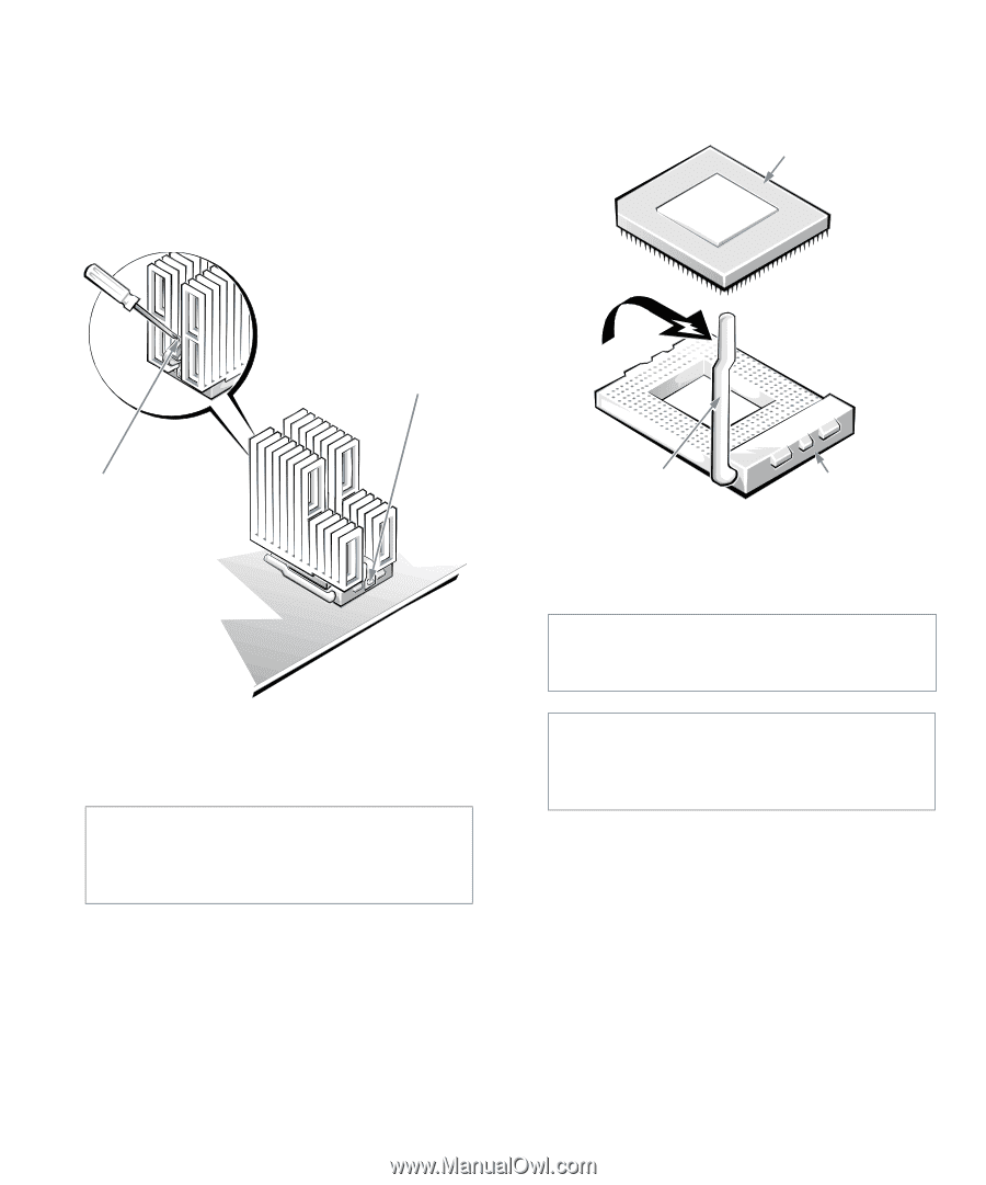
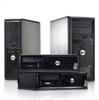
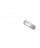
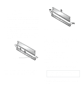
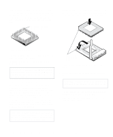
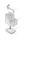
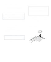
3. Remove the metal clip that secures the heat sink to the microprocessor socket. Then remove the heat sink from the microprocessor chip. Press down on the folded part of the clip with a small screwdriver to release the clip (see Figure 6-9). The securing clip hooks over tabs on the sides of the socket. socket. Leave the release lever extended so that the socket is ready for the new microprocessor. microprocessor chip securing clip press here to release securing clip Figure 6-9. Microprocessor Heat Sink 4. Remove the microprocessor chip from the socket. CAUTION: Be careful not to bend any of the pins when removing the microprocessor chip from its socket. Bending the pins can permanently damage the microprocessor chip. Your microprocessor socket is a zero insertion force (ZIF) socket with a lever-type handle that secures the chip in, or releases it from, the socket. To remove the chip, pull the microprocessor-socket release lever straight out until the chip is released (see Figure 6-10). Then remove the chip from the release lever microprocessor socket Figure 6-10. Removing the Microprocessor 5. Unpack the new microprocessor. CAUTION: Ground yourself by touching an unpainted metal surface on the back of the computer. CAUTION: Be careful not to bend any of the pins when unpacking the microprocessor. Bending the pins can permanently damage the microprocessor. If any of the pins on the chip appear to be bent, see the chapter titled "Getting Help" in your Diagnostics and Troubleshooting Guide for instructions on obtaining technical assistance. 6. Align the pin-1 corner of the microprocessor chip (see Figure 6-11) with the pin-1 corner of the microprocessor socket (see Figure 6-12). NOTE: Identifying the pin-1 corners is critical to positioning the chip correctly. Installing System Board Options 6-7
-
 1
1 -
2
-
3
-
4
-
5
-
6
-
7
-
8
-
9
-
10
-
11
-
12
-
13
-
14
-
15
-
16
-
17
-
18
-
19
-
20
-
21
-
22
-
23
-
24
-
25
-
26
-
27
-
28
-
29
-
30
-
31
-
32
-
33
-
34
-
35
-
36
-
37
-
38
-
39
-
40
-
41
-
42
-
43
-
44
-
45
-
46
-
47
-
48
-
49
-
50
-
51
-
52
-
53
-
54
-
55
-
56
-
57
-
58
-
59
-
60
-
61
-
62
-
63
-
64
-
65
-
66
-
67
-
 68
68 -
 69
69 -
 70
70 -
 71
71 -
 72
72 -
 73
73 -
 74
74 -
 75
75 -
 76
76 -
 77
77 -
 78
78 -
79
-
80
-
81
-
82
-
83
-
84
-
85
-
86
-
87
-
88
-
89
-
90
-
91
-
92
-
93
-
94
-
95
-
96
-
97
-
98
-
99
-
100
-
101
-
102
-
103
-
104
-
105
-
106
-
107
-
108
-
109
-
110
-
111
-
112
-
113
-
114
-
115
-
116
-
117
-
118
-
119
-
120
-
121
-
122
-
123
-
124
-
125
-
126
 |
 |