Dell OptiPlex Gn Reference and Installation Guide (.pdf) - Page 66
System Board Labels, Table 5-2., System Board and Riser Board Connectors and Sockets
 |
View all Dell OptiPlex Gn manuals
Add to My Manuals
Save this manual to your list of manuals |
Page 66 highlights
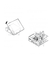
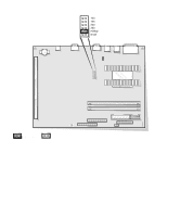
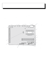
System Board Labels Table 5-2 lists the connectors and sockets on your system board and riser board, and it gives a brief description of their functions. Table 5-2. System Board and Riser Board Connectors and Sockets Connector or Socket Description BATTERY Battery socket DIMM_x DIMM socket DSKT Diskette/tape drive interface connector ENET HDLED IDEn ISAn* KYBD NIC connector (optional) Hard-disk drive LED connector (on riser board) EIDE interface connector ISA expansion-card connector (on riser board) Keyboard connector MICROPROCESSOR MONITOR MOUSE P1 Microprocessor socket Video connector Mouse connector Wakeup On LAN power connector (on riser board) PANEL PARALLEL PCIn* POWER_1 POWER_2 Control panel connector Parallel port connector; sometimes referred to as LPT1 PCI expansion-card connector (on riser board) Main power input connector 3.3-V power input connector RISER Riser board connector SERIALn Serial port connector; sometimes referred to as COMn USB USB connectors * The ISA1/PCI2 connector pair shares a single card-slot opening, so only one of the two connectors can be used at a time. NOTE: For the full name of an abbreviation or acronym used in this table, see the Glossary in your online System User's Guide. 5-8 Dell OptiPlex Gn and Gn+ Low-Profile Systems Reference and Installation Guide
-
 1
1 -
2
-
3
-
4
-
5
-
6
-
7
-
8
-
9
-
10
-
11
-
12
-
13
-
14
-
15
-
16
-
17
-
18
-
19
-
20
-
21
-
22
-
23
-
24
-
25
-
26
-
27
-
28
-
29
-
30
-
31
-
32
-
33
-
34
-
35
-
36
-
37
-
38
-
39
-
40
-
41
-
42
-
43
-
44
-
45
-
46
-
47
-
48
-
49
-
50
-
51
-
52
-
53
-
54
-
55
-
56
-
57
-
58
-
59
-
60
-
 61
61 -
 62
62 -
 63
63 -
 64
64 -
 65
65 -
 66
66 -
 67
67 -
 68
68 -
 69
69 -
 70
70 -
 71
71 -
72
-
73
-
74
-
75
-
76
-
77
-
78
-
79
-
80
-
81
-
82
-
83
-
84
-
85
-
86
-
87
-
88
-
89
-
90
-
91
-
92
-
93
-
94
-
95
-
96
-
97
-
98
-
99
-
100
-
101
-
102
-
103
-
104
-
105
-
106
-
107
-
108
-
109
-
110
-
111
-
112
-
113
-
114
-
115
-
116
-
117
-
118
-
119
-
120
-
121
-
122
-
123
-
124
-
125
-
126
 |
 |