Dell OptiPlex Gn Reference and Installation Guide (.pdf) - Page 72
Installing a DIMM, Removing a DIMM, Upgrading the Microprocessor
 |
View all Dell OptiPlex Gn manuals
Add to My Manuals
Save this manual to your list of manuals |
Page 72 highlights
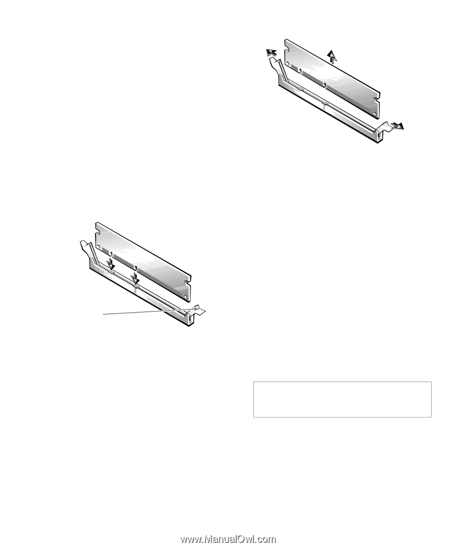
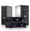
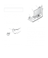
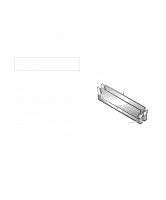
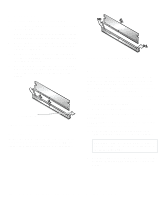
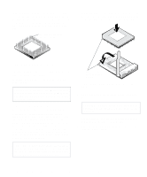
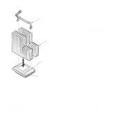
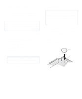
Installing a DIMM Use the following procedure to install a DIMM: 1. Locate the first empty socket in which you plan to install a DIMM. DIMMs should be installed in consecutive sockets beginning with socket A for optimum performance. 2. Locate the plastic securing clips at each end of the socket. Press the clips outward until they snap open (see Figure 6-7). 3. Orient the DIMM to the socket by aligning the notches in the DIMM's edge connector with the crossbars in the socket. 4. Press the DIMM straight into the slot running down the center of the socket until the securing clips snap into place around the ends of the DIMM. securing clips (2) Figure 6-7. Installing a DIMM Removing a DIMM To remove a DIMM, press the securing clips outward (see Figure 6-8) simultaneously until the DIMM disengages from the socket (it should pop out slightly). Figure 6-8. Removing a DIMM Upgrading the Microprocessor To take advantage of future options in speed and functionality, you can replace the microprocessor on your system board with any Dell-supported microprocessor upgrade. Call your Dell sales representative for information on available microprocessor upgrades. The following items are included in a microprocessor upgrade kit: • The new microprocessor chip • A new heat sink with thermal interface adhesive The following procedure describes how to replace the microprocessor. NOTE: Dell recommends that only a technically knowledgeable person perform this procedure. 1. Remove the computer cover as instructed in "Removing the Computer Cover" in Chapter 5. CAUTION: See "Protecting Against Electrostatic Discharge" in the safety instructions at the front of this guide. 2. See Figure 6-1 to locate the microprocessor socket (labeled "MICROPROCESSOR") on the system board. 6-6 Dell OptiPlex Gn and Gn+ Low-Profile Systems Reference and Installation Guide
-
 1
1 -
2
-
3
-
4
-
5
-
6
-
7
-
8
-
9
-
10
-
11
-
12
-
13
-
14
-
15
-
16
-
17
-
18
-
19
-
20
-
21
-
22
-
23
-
24
-
25
-
26
-
27
-
28
-
29
-
30
-
31
-
32
-
33
-
34
-
35
-
36
-
37
-
38
-
39
-
40
-
41
-
42
-
43
-
44
-
45
-
46
-
47
-
48
-
49
-
50
-
51
-
52
-
53
-
54
-
55
-
56
-
57
-
58
-
59
-
60
-
61
-
62
-
63
-
64
-
65
-
66
-
 67
67 -
 68
68 -
 69
69 -
 70
70 -
 71
71 -
 72
72 -
 73
73 -
 74
74 -
 75
75 -
 76
76 -
 77
77 -
78
-
79
-
80
-
81
-
82
-
83
-
84
-
85
-
86
-
87
-
88
-
89
-
90
-
91
-
92
-
93
-
94
-
95
-
96
-
97
-
98
-
99
-
100
-
101
-
102
-
103
-
104
-
105
-
106
-
107
-
108
-
109
-
110
-
111
-
112
-
113
-
114
-
115
-
116
-
117
-
118
-
119
-
120
-
121
-
122
-
123
-
124
-
125
-
126
 |
 |