Dell OptiPlex Gn Reference and Installation Guide (.pdf) - Page 81
Connecting Drives, Installing a Drive in the 5.25-Inch Drive Bay,
 |
View all Dell OptiPlex Gn manuals
Add to My Manuals
Save this manual to your list of manuals |
Page 81 highlights
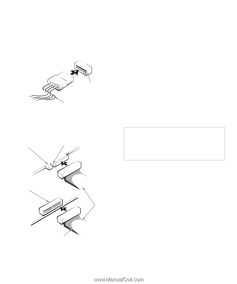
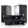
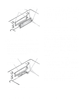
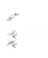
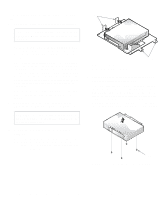
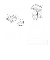
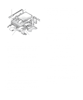
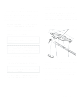
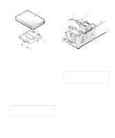
Connecting Drives When installing a drive, you connect two cables-a direct current (DC) power cable and an interface cable- to the back of the drive. Your drive's power input connector (to which you connect the DC power cable) resembles the connector shown in Figure 7-4. power input connector DC power cable Figure 7-4. DC Power Cable Connector The drive's interface connector is a header connector, as shown in Figure 7-5. card-edge connector on drive notch When attaching the interface cable to a drive, be sure to match the colored strip on the cable to pin 1 of the drive's interface connector. For the location of pin 1 on the drive's interface connector, see the documentation that came with the drive. When disconnecting an interface cable from the system board, be sure to press in on the locking tabs on the cable connector before disconnecting the cable. When attaching an interface cable to the system board, be sure that the locking tabs snap into place, ensuring that the cable is firmly attached to the connector on the system board. Most interface connectors are keyed for correct insertion; that is, a notch or a missing pin on one connector matches a tab or a filled-in hole on the other connector. Keying ensures that the pin-1 wire in the cable (indicated by the colored strip along one edge of the cable) goes to the pin-1 end of the connector. The pin-1 end of a connector on a board or a card is usually indicated by a silk-screened "1" printed directly on the board or card. CAUTION: When connecting an interface cable, do not reverse the interface cable (do not place the colored strip away from pin 1 on the connector). Reversing the cable prevents the drive from operating and could damage the controller, the drive, or both. header connector on drive interface cables colored strip Figure 7-5. Drive Interface Connectors Installing a Drive in the 5.25-Inch Drive Bay The 5.25-inch drive bay can accommodate any of the following types of drives: • A diskette drive or tape drive that uses the diskette/ tape drive interface on the system board • A CD-ROM or tape drive that uses the secondary EIDE interface on the system board • A CD-ROM or tape drive that uses its own controller card Installing Drives 7-3
-
 1
1 -
2
-
3
-
4
-
5
-
6
-
7
-
8
-
9
-
10
-
11
-
12
-
13
-
14
-
15
-
16
-
17
-
18
-
19
-
20
-
21
-
22
-
23
-
24
-
25
-
26
-
27
-
28
-
29
-
30
-
31
-
32
-
33
-
34
-
35
-
36
-
37
-
38
-
39
-
40
-
41
-
42
-
43
-
44
-
45
-
46
-
47
-
48
-
49
-
50
-
51
-
52
-
53
-
54
-
55
-
56
-
57
-
58
-
59
-
60
-
61
-
62
-
63
-
64
-
65
-
66
-
67
-
68
-
69
-
70
-
71
-
72
-
73
-
74
-
75
-
 76
76 -
 77
77 -
 78
78 -
 79
79 -
 80
80 -
 81
81 -
 82
82 -
 83
83 -
 84
84 -
 85
85 -
 86
86 -
87
-
88
-
89
-
90
-
91
-
92
-
93
-
94
-
95
-
96
-
97
-
98
-
99
-
100
-
101
-
102
-
103
-
104
-
105
-
106
-
107
-
108
-
109
-
110
-
111
-
112
-
113
-
114
-
115
-
116
-
117
-
118
-
119
-
120
-
121
-
122
-
123
-
124
-
125
-
126
 |
 |