Dell OptiPlex Gn Reference and Installation Guide (.pdf) - Page 75
Replacing the System Battery, Installing the Heat Sink
 |
View all Dell OptiPlex Gn manuals
Add to My Manuals
Save this manual to your list of manuals |
Page 75 highlights
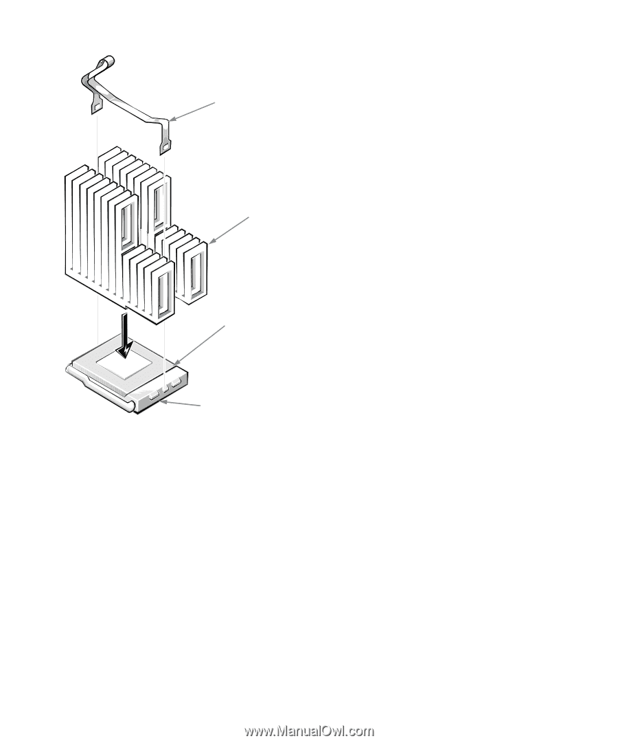
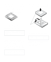
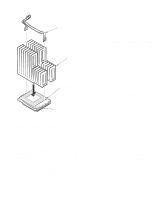
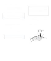
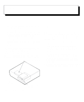
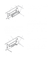
clip heat sink 12. Replace the computer cover, and then reconnect your computer and peripherals to their power sources and turn them on. As the system boots, it detects the presence of the new microprocessor and automatically changes the system configuration information in the System Setup program. 13. Enter the System Setup program, and confirm that the Microprocessor category correctly identifies the installed microprocessor. See Chapter 2, "Using the System Setup Program." 14. Run the Dell Diagnostics to verify that the new microprocessor is operating correctly. See your Diagnostics and Troubleshooting Guide for information on running the Dell Diagnostics and troubleshooting any problems that may occur. microprocessor chip microprocessor socket Figure 6-13. Installing the Heat Sink 10. Replace the heat sink securing clip. Orient the clip as shown in Figure 6-13, and hook the unfolded end of the clip over the tab on the top edge of the socket. Then press down on the folded end of the clip to snap the clip over the tab on the bottom edge of the socket. 11. If necessary, change the microprocessor speed jumper setting (see Figure 5-7 to locate the system board jumpers). The microprocessor speed jumper should be set for the installed microprocessor's rated internal speed. For example, for a 166-megahertz (MHz) Intel Pentium processor, a jumper plug should be installed on the pins labeled "166." (See Table 5-1 for more information.) Replacing the System Battery A 3.0-volt (V) CR2032 coin-cell battery installed on the system board maintains system configuration, date, and time information in a special section of memory. The operating life of the battery can extend up to ten years. The battery may need replacing if an incorrect time or date is displayed during the boot routine along with a message such as: Time-of-day not set - please run SETUP program or Invalid configuration information - please run SETUP program or Strike the F1 key to continue, F2 to run the setup utility To determine whether the battery needs replacing, reenter the time and date through the System Setup program (not through the MS-DOS time and date commands) and exit the program properly to save the information (see Chapter 2, "Using the System Setup Program," for instructions). Turn off and disconnect your system from alternating current (AC) power for a few hours; then reconnect and turn on your system. Enter the System Installing System Board Options 6-9
-
 1
1 -
2
-
3
-
4
-
5
-
6
-
7
-
8
-
9
-
10
-
11
-
12
-
13
-
14
-
15
-
16
-
17
-
18
-
19
-
20
-
21
-
22
-
23
-
24
-
25
-
26
-
27
-
28
-
29
-
30
-
31
-
32
-
33
-
34
-
35
-
36
-
37
-
38
-
39
-
40
-
41
-
42
-
43
-
44
-
45
-
46
-
47
-
48
-
49
-
50
-
51
-
52
-
53
-
54
-
55
-
56
-
57
-
58
-
59
-
60
-
61
-
62
-
63
-
64
-
65
-
66
-
67
-
68
-
69
-
 70
70 -
 71
71 -
 72
72 -
 73
73 -
 74
74 -
 75
75 -
 76
76 -
 77
77 -
 78
78 -
 79
79 -
 80
80 -
81
-
82
-
83
-
84
-
85
-
86
-
87
-
88
-
89
-
90
-
91
-
92
-
93
-
94
-
95
-
96
-
97
-
98
-
99
-
100
-
101
-
102
-
103
-
104
-
105
-
106
-
107
-
108
-
109
-
110
-
111
-
112
-
113
-
114
-
115
-
116
-
117
-
118
-
119
-
120
-
121
-
122
-
123
-
124
-
125
-
126
 |
 |