Dell OptiPlex Gn Reference and Installation Guide (.pdf) - Page 63
Inside the Chassis, circuit board so that you can identify each pin number
 |
View all Dell OptiPlex Gn manuals
Add to My Manuals
Save this manual to your list of manuals |
Page 63 highlights
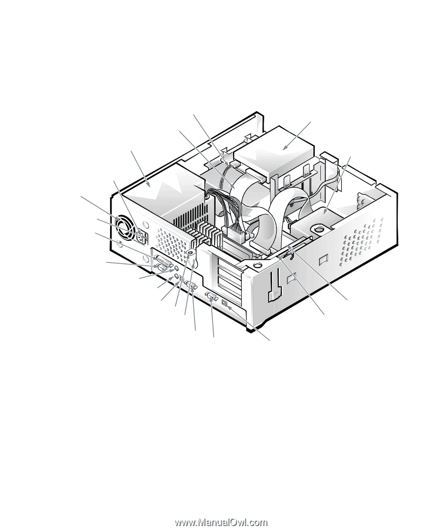
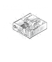
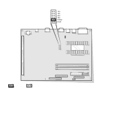
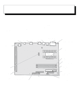
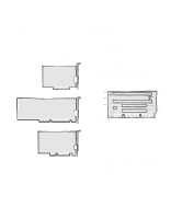
A jumper is referred to as open or unjumpered when the plug is pushed down over only one pin or if there is no plug at all. When the plug is pushed down over two pins, the jumper is referred to as jumpered. In some documents, the jumper setting may be shown in text as two numbers, such as 1-2. The number 1 is printed on the DC power cable drive interface cable power supply AC power receptacle fan guard voltage selection switch parallel port connector circuit board so that you can identify each pin number based on the location of pin 1. Figure 5-7 shows the location and default settings of the jumper blocks on your system board. See Table 5-1 for the designations, default settings, and functions of your system's jumpers. drive in upper bay hard-disk drive serial port 1 connector mouse connector keyboard connector USB connectors padlock ring back of computer security cable slot serial port 2 connector Figure 5-6. Inside the Chassis system board expansion-card cage video connector NIC connector (optional) Working Inside Your Computer 5-5
-
 1
1 -
2
-
3
-
4
-
5
-
6
-
7
-
8
-
9
-
10
-
11
-
12
-
13
-
14
-
15
-
16
-
17
-
18
-
19
-
20
-
21
-
22
-
23
-
24
-
25
-
26
-
27
-
28
-
29
-
30
-
31
-
32
-
33
-
34
-
35
-
36
-
37
-
38
-
39
-
40
-
41
-
42
-
43
-
44
-
45
-
46
-
47
-
48
-
49
-
50
-
51
-
52
-
53
-
54
-
55
-
56
-
57
-
 58
58 -
 59
59 -
 60
60 -
 61
61 -
 62
62 -
 63
63 -
 64
64 -
 65
65 -
 66
66 -
 67
67 -
 68
68 -
69
-
70
-
71
-
72
-
73
-
74
-
75
-
76
-
77
-
78
-
79
-
80
-
81
-
82
-
83
-
84
-
85
-
86
-
87
-
88
-
89
-
90
-
91
-
92
-
93
-
94
-
95
-
96
-
97
-
98
-
99
-
100
-
101
-
102
-
103
-
104
-
105
-
106
-
107
-
108
-
109
-
110
-
111
-
112
-
113
-
114
-
115
-
116
-
117
-
118
-
119
-
120
-
121
-
122
-
123
-
124
-
125
-
126
 |
 |