Dell OptiPlex Gn Reference and Installation Guide (.pdf) - Page 69
Removing the Filler Bracket, Installing an Expansion Card
 |
View all Dell OptiPlex Gn manuals
Add to My Manuals
Save this manual to your list of manuals |
Page 69 highlights
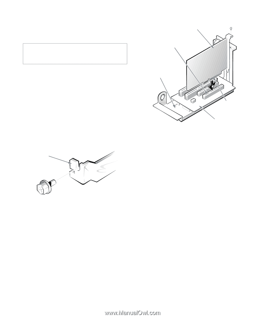
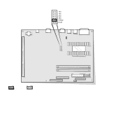
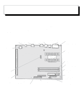
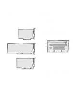
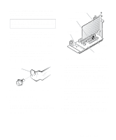
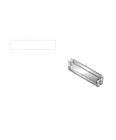
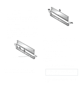
2. Prepare the expansion card for installation, and remove the computer cover as instructed in "Removing the Computer Cover" in Chapter 5. CAUTION: See "Protecting Against Electrostatic Discharge" in the safety instructions at the front of this guide. See the documentation that came with the expansion card for information on configuring the card, making internal connections, or otherwise customizing it for your system. 3. Remove the expansion-card cage as instructed in "Removing the Expansion-Card Cage" in Chapter 5. 4. Unscrew and remove the metal filler bracket that covers the card-slot opening for the expansion slot you intend to use (see Figure 6-4). Save the screw to use when installing the expansion card later in this procedure. filler bracket Figure 6-4. Removing the Filler Bracket 5. Install the expansion card. Position the expansion-card cage so that the riser board lies horizontally on your work surface. Insert the card-edge connector firmly into the expansion-card connector on the riser board. Gently rock the card into the connector until it is fully seated (see Figure 6-5). expansion card expansion-card connector expansion-card cage card-edge connector riser board Figure 6-5. Installing an Expansion Card 6. When the card is firmly seated in the connector and the card-mounting bracket is flush with the brackets on either side of it, secure the bracket with the screw you removed in step 4. 7. If you are installing an optional Wakeup On LAN-capable network card, attach the three-wire power cable that came with the card to the P1 connector on the riser board (see Figure 6-3) and to the network card. 8. Replace the expansion-card cage in the chassis as instructed in "Replacing the Expansion-Card Cage" in Chapter 5. 9. Connect any cables that should be attached to the card. See the documentation that came with the card for information about its cable connections. 10. Replace the computer cover, and then reconnect your computer and peripherals to their power sources and turn them on. Installing System Board Options 6-3
-
 1
1 -
2
-
3
-
4
-
5
-
6
-
7
-
8
-
9
-
10
-
11
-
12
-
13
-
14
-
15
-
16
-
17
-
18
-
19
-
20
-
21
-
22
-
23
-
24
-
25
-
26
-
27
-
28
-
29
-
30
-
31
-
32
-
33
-
34
-
35
-
36
-
37
-
38
-
39
-
40
-
41
-
42
-
43
-
44
-
45
-
46
-
47
-
48
-
49
-
50
-
51
-
52
-
53
-
54
-
55
-
56
-
57
-
58
-
59
-
60
-
61
-
62
-
63
-
 64
64 -
 65
65 -
 66
66 -
 67
67 -
 68
68 -
 69
69 -
 70
70 -
 71
71 -
 72
72 -
 73
73 -
 74
74 -
75
-
76
-
77
-
78
-
79
-
80
-
81
-
82
-
83
-
84
-
85
-
86
-
87
-
88
-
89
-
90
-
91
-
92
-
93
-
94
-
95
-
96
-
97
-
98
-
99
-
100
-
101
-
102
-
103
-
104
-
105
-
106
-
107
-
108
-
109
-
110
-
111
-
112
-
113
-
114
-
115
-
116
-
117
-
118
-
119
-
120
-
121
-
122
-
123
-
124
-
125
-
126
 |
 |