Epson 2070 Service Manual
Epson 2070 - LQ B/W Dot-matrix Printer Manual
 |
UPC - 010343812277
View all Epson 2070 manuals
Add to My Manuals
Save this manual to your list of manuals |
Epson 2070 manual content summary:
- Epson 2070 | Service Manual - Page 1
EPSON TERMINAL PRINTER LQ-2070 SERVICE MANUAL EPSON 4006244 - Epson 2070 | Service Manual - Page 2
NOTICE • All right reserved. Reproduction of any part of this manual in any form wharsoever without SEIKO EPSON's express written permission is forbidden. • The contents of this manual are subject to change without notice. • All efforts have been made to ensure the accuracy of the contents of this - Epson 2070 | Service Manual - Page 3
performing procedures preceded by a DANGER headings. WARNING Singnals a precaution which, CONNECT THE UNIT TO A POWER SOURCE UNIT INSTRUCTED TO DO SO. WHEN THE POWER SUPPLY CABLE THAT THE EPSON PRODUCT HAS BEEN DISCONNECTED FROM THE POWER SOURCE BEFORE REMOVING OR REPLACING PRINTED CIRCUIT BOARDS - Epson 2070 | Service Manual - Page 4
2 - Describes the theory of printer operation. Chapter 3 - Includes a step-by-step guide for product disassembly and assembly. Chapter 4 - Includes a step-by step guide for addjustement. Chapter 5 - Provides Epson-approved techniques for troubleshooting. Chapter 6 - Describes prevetive maintenance - Epson 2070 | Service Manual - Page 5
Revision Rev. A REVISION SHEET Issued Date April 8,1996 Revision Page 1st issued - Epson 2070 | Service Manual - Page 6
TABLE OF CONTENTS CHAPTER 1. CHAPTER 2. CHAPTER 3. CHAPTER 4. CHAPTER 5. CHAPTER 6. APPENDIX GENERAL DESCRIPTION OPERATION PRINCIPLES DISASSEMBLY AND ASSEMBLY ADJUSTMENTS TROUBLESHOOTING MAINTENANCE - Epson 2070 | Service Manual - Page 7
Accessories 1-3 1.2 Hardware Specifications 1-4 1.2. I Printing Method 1-4 1.2.2 Printing Specifications 1 - 5 1.2.3 Paper Handling Specifications 1-6 1.2.4 Paper Specifications 1-8 1.2.5 Ribbon Specifications 1-16 1.2.6 Electrical Specifications 1-16 1.2.7 Environmental Conditions - Epson 2070 | Service Manual - Page 8
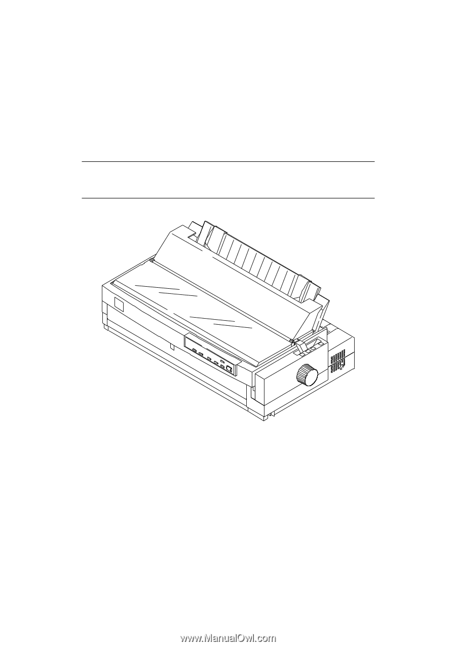
C166 PSB/PSE Board Assembly 1-36 1.6.3 C165 PNL Board Assembly 1-37 1.6.4 Printer Mechanism 1-37 1.6.5 Housing Assembly 1-38 List of Figures Figure 1-1. Exterior View of the LQ-2070 1-2 Figure l-2. Pin Configuration 1-4 Figure 1-3. Printable Area for Cut Sheets 1-9 Figure 1-4. Printable - Epson 2070 | Service Manual - Page 9
Included with the Printer 1-3 Table 1-2. Consumables 1-3 Table 1-3. Optional Units 1-3 Table l-4. PrintSpeed and Printable Columns 1-5 Table l-5. Print Resolution 1-5 Table 1-6. Paper Path and Paper Types 1-6 Table l-7. PaperThickness Lever Positions 1'7 Table 1-8. Specifications for Cut - Epson 2070 | Service Manual - Page 10
LQ-2070 Sendce Manual Product Description 1.1 Specifications These specifications provide statistical information for the LQ-2070 serial impact dot matrix printer. 1.1.1. Features The LQ-2070 is a 24pin serial impact dot-matrix printer suitable for the VAR (value addedreseller) market. The major - Epson 2070 | Service Manual - Page 11
Product Description LQ-2070 Service Manual Figure 1-1 Exterior View of the LQ-2070 1-2 Rev.A - Epson 2070 | Service Manual - Page 12
LCk2070 Service Manual Product Description 1.1.2. Accessories q Items included in the printer carton Table 1-1 Items Included with the Printer Enclosed Items User's guide Driver diskette Ribbon cartridge Power cord Quantity 1 1 1 1 . Consumables Table 1-2 Consumables Consumable Item Ribbon - Epson 2070 | Service Manual - Page 13
Product Description LQ-2070 Servioe Manual 1.2 Hardware Specifications This section provides detailed hardware specifications for the LQ-2070. 1.2.1 Printing Method . l?rintig method . Color . Number of pins . Pin arrangement q print Pin diameter Impact dot matrix Black 24 pins 12x 2 staggered - Epson 2070 | Service Manual - Page 14
LQ-2070 Service Manual Product Description 1.2.2 Printing Specifications q Copy capability q Print speed and printable columns 1 original+ 3copies Table 1-4 Print Speed and Printable Columns Print Mode High-speed draft Draft Draft condensed LQ LQ Condensed Character Pitch 10 cpi 10 cpi 12 cpi - Epson 2070 | Service Manual - Page 15
Product Description LQ-2070 Service Manual 1.2.3 Paper Handling Specifications q Feeding method Friction feed Push tractor feed Push and pull tractor feed (front, rear) (front, rear) (front, rear, bottom) . Feeder Front push tractor(option), mar - Epson 2070 | Service Manual - Page 16
LQ-2070 Service Manual Product Description . Paper thickness lever Set the paper thickness lever to the appropriate position, as indicated in the following table. Table 1-7 Paper Thickness Lever Positions - Epson 2070 | Service Manual - Page 17
Product Description LQ-2070 Service Manual 4. Push-pull tractor feed q Set the release lever to the REAR PUSH that can be used in this printer. Cut Sheets q Paper/ media specifications The following table shows specifications for cut sheets. Table 1-8 Specifications for Cut Sheets (Single Sheet, - Epson 2070 | Service Manual - Page 18
LC?-2070 Service Manual Product Description q Printable area Figure 1-3 shows the printable area for cut 3 mm (0.12") or more (PW ~ 364 mm (14.33")) 25 mm (0.98") or more (PW = 420 mm (16.5")) 3 mm or more (PWs 364 mm (14.33")) 25 mm (0.98") or more (PW = 420 mm (16.5")) 4.2 mm (0.17") or more 4.2 - Epson 2070 | Service Manual - Page 19
LQ-2070 Service Manual Envelopes and Card Stock q Paper/media specifications The following tables gives specifications for envelopes and card stock. Table 1-11 Specifications . Not curled. not folded. or not C~MDled. % Printing on envelopes is available only at normal temperatures and humidity. - Epson 2070 | Service Manual - Page 20
LQ-2070 Service Manual Product Description q Printable area The figure below shows the printable area for envelopes and card stock. Each ~bbreviation is defined-in the following table. - Table 1- - Epson 2070 | Service Manual - Page 21
LQ-2070 Service Manual Continuous Paper q Paper/media specifications The following table gives specifications continuous paper. Table 1-14 Specifications 12 lb) (15 lb) Plain paper. Recycled paper. Carbonless multipart. Dots of glue or paper staples (both sides). Minimum Maximum 101 mm - Epson 2070 | Service Manual - Page 22
LQ-2070 Service Manual Product Description q Printable area The figure below shows the printable area for continuous paper. Each abbreviation is defined in the following table. Table 1-15 Printable - Epson 2070 | Service Manual - Page 23
LQ-2070 Service Manuai Continuous Paper with Labels q Paper/media specifications The following table gives the specifications for continuous paper with labels. Table 1-16 Specifications Avery mini-line or equivalent quality labels % Printing on labels is available only at normal temperatures - Epson 2070 | Service Manual - Page 24
Lt2-2070 Service Manual Product Description Roll Paper Note: Roll paper is not available in all models, and not available in the U.S. . Paper/media specifications The following table shows specifications for roll paper. Table 1-17 Specifications for Roll Paper I I I Front Entry Rear Entry - Epson 2070 | Service Manual - Page 25
Product Description LQ-2070 Service Manuai 1.2.5 Ribbon Specifications Table 1-19 Statistics on the Ribbon Item Type Color Ribbon life Dimension Specification Fabric Black 8 million characters (draft, 10 cpi, 48dotcJ character) 506.0 mm (W) x 123.5 mm (D) x 23.0 mm (H) 19.92" (W) X 4.86" (D) X . - Epson 2070 | Service Manual - Page 26
LQ-2070 Service Manual Product Description 1.2.7 Environmental Conditions Table 1-22 explains the conditions the printer requires during operation and when not operating, Table 1-22 Environmental Requirements Item I Specifications Temperature 5 to 35° C/41 to 95° F ( operating %1) 15to 25° C/ - Epson 2070 | Service Manual - Page 27
Weighing Instruments Directive 90/384/EEC LQ-2070 Service Manual EN60950 EN55022 class B EN50082-1 , IEC801-2 IEC801-3 , IEC801-4 EN45501 1.2.11 Physical Specifications Table 1-26 provides printer dimensions and weight. Table 1-26 Physical Specifications Dimensions 639 mm (W) x402 mm (D) x 257 - Epson 2070 | Service Manual - Page 28
LQ-2070 Service Manual . Stacker capacity Table 1-28 Capacity of the Stacker Product Description CSF Bin 1 CSF Bin 2 Single sheets 140 sheets (+$ 1) ---- 100 sheets (~ 2) Envelopes 15 sheets (% 3) ---- 28 sheets (% 4) - Epson 2070 | Service Manual - Page 29
LQ-2070 Service Manual 1.3 Firmware Specifications This section provides detailed information about LQ-2070 firmware. 1.3.1 Control Codes and Fonts q Control codes ESC/P2 and IBM 2390/2391 plus emulations. q Typefaces Bitmap fonts EPSON Draft EPSON Roman EPSON Saris Serif EPSON Courier EPSON - Epson 2070 | Service Manual - Page 30
LQ-2070 Service Manual Product Description 1.3.2 Interface Specifications This printer provides a bidirectional 8-bit parallel interface and a Type B optional interface slot, standard. 1.3.2.1 Parallel Interface (Fotward Channel) q Transmission mode q Adaptable connector q Synchronization . - Epson 2070 | Service Manual - Page 31
Product Description DATA LC?-2070 Service Manual 'T R O B E ~tsetu~< tstb ! BUSY 1 I &! treadv~l> tbusy ACKNLG I I p-r Figure 1-8 Data Transmission Timing Table 1-32 Maximum and Minimum Timings for Data Transmission Parameter setup thold t stb tready tbusy - Epson 2070 | Service Manual - Page 32
LQ-2070 Service Manual Product Description 1.3.2.2 Parallel Interface (Reverse Channel) q Transmission mode IEEE-P1284 nibble mode . Adaptable comector 57-30360 (Anphenol) or equivalent q Synchronization Refer to the IEEE-P1284 Specification out Printer clock signal. out Printer busy - Epson 2070 | Service Manual - Page 33
Product Description LQ-2070 Service Manual q Extensibility request The printer responds to the ESC/P2 [00 H][32 H MFG: EPSON, CMD: ESCPC2-00, MDL: LQ-2070, CLS: PRINTER IBM2391 ph.Is [00 H][33H MGF: EPSON, CMD: PRPXL24-01, MDL: LQ-2070, CLS: PRINTER 1.3.2.3 Interface Selection The printer - Epson 2070 | Service Manual - Page 34
LQ-2070 Service Manual Product Description 1.3.3 Paper Handling Sequence In this section, paper handling firmware sequences are described in several cases. q Printer status Printer is on line (not in the pause state). No PE sensor detects that paper is loaded. The release lever position is set - Epson 2070 | Service Manual - Page 35
LQ-2070 Service Manual . Printer status The front PE sensor detects that paper is loaded in the front paper path. The release lever is set to continuous paper Table 1-36 Paper Handling Sequence 3 Occurrence Result PAUSE button pressed Printer goes off or on line. LF/FF button rxessed Printer - Epson 2070 | Service Manual - Page 36
LQ-2070 Service Manual Product Description q Printer status The rear PE sensor detects that paper is forward. Micro Adjust ? button pressed Micro Adjust $ button pressed The printer micro feeds paper fotward. The printer micro feeds paper backward. I Release lever set to tractor position - Epson 2070 | Service Manual - Page 37
2070 Service Manual 1.3.4. Paper Width (PW) Sensor Operation The PW sensor is mounted on the ribbon mask holder to measure the paper width and detect the top edge of the paper. However, in cases where print than 30 columns) is loaded, the printer changes the centering position to the proper position, - Epson 2070 | Service Manual - Page 38
LC?-2070 Service Manual Product Description 1.4 Operating Instructions This section provides detailed information about the LQ-2070 control panel buttons and LEDs. 1.4.1 Control Panel Operations The printer control panel contains 6 non-lock type push buttons and 8 LEDs for various printer - Epson 2070 | Service Manual - Page 39
LQ-2070 Service Manual q Operations at power on Turning the printer on while pressing panel buttons executes the functions below: Table 1-42 Operation at Power On Button Function Load / Eject LF I FF LQ Paper Jam On Blinks -- --- -.. q 0000 Head Hot Blinks --- .- .-. . . . --- - Epson 2070 | Service Manual - Page 40
LQ-2070 Service Manual Product Description 1.4.3 Micro Adjust Function The micro adjust function lets you set the TOF and tear off positions. After the printer position when any new print data is sent to the printer. The tear off position is saved in the EEPROM, and if the printer is turned off, - Epson 2070 | Service Manual - Page 41
LQ-2070 Sewice Manual 1.4.5 Self-test Function Pressing the Load / Eject button while turning on the printer puts the printer in LQ self-test mode. Pressing the LF/FF button while turning on the printer puts the printer CSF is in use. The self-test prints out the following: 0 The maximum number - Epson 2070 | Service Manual - Page 42
LQ-2070 Service Manual Product Description 1.4.7 Default Setting Function Pressing the Pitch button while turning on the printer puts the printer in default setting mode. Some default printer settings can be changed in this operation. The method for setting defaults is described in the instruction - Epson 2070 | Service Manual - Page 43
Product Description LQ-2070 Service Manual 1.4.9 Bidirectional Adjustment Function Pressing the Pause button while turning on the printer puts the printer in bidirectional adjustment mode. In this mode, you can adjust the bidirectional alignment for the following three modes: 1. Draft mode 2. - Epson 2070 | Service Manual - Page 44
LC?-2070 Service Manual Product Description 1.6 MAIN COMPONENTS The main components of the LQ-2070 are designed for easy removal and repair. The main components are: 0 C186 MAIN Board Assembly 0C166PSB/PSE Board Assembly (120 V/230V) 0 C165 PNL Bowd Assembly 0 Printer Mechanism Cl HousingAssembly - Epson 2070 | Service Manual - Page 45
LQ-2070 Service Manual 1.6.1 C186 MAIN Board Assembly The C186 MAIN board consists of a TMP96C041AF CPU, an E05B13 gate array, a program/CG ROM, a PS-IWM, an EEPROM, etc. Head Driva TRANSISTOR IC 5 PS RAM ICI 1,14 PF Motor Driver TEA3718SDP 1 1 ~n D .H / \ IC12 CR Motor Driver printer - Epson 2070 | Service Manual - Page 46
Product Description LQ-2070 Service Manual 1.6.5. Housing Assembly This consists of printer cover assembly, edge guide assembly, upper housing, lower housing assembly, etc. Figure 1:17 Housing Assembly 1-38 Rev.A - Epson 2070 | Service Manual - Page 47
Contents 2.1 PRINTER MECHANISM OPERATION 2-1 2.1.1 Printing Mechanism 2-1 2.1.2 Carriage Movement Mechanism 2-2 2.1.3. Platen Gap Adjustment 2-3 2.1.4 Paper Handling Mechanism 2-4 2.1.4.1 Release Lever 2-4 2.1.4.2 Paper Advance Mechanism 2-5 2.1.5 Paper Paths 2-11 2.1.6 Ribbon Advance - Epson 2070 | Service Manual - Page 48
2-36. PF Motor Driver Circuit 2-26 Figure 2-37. EEPROM Control Circuit 2-26 Figure 2-38. Sensor Circuit 2-27 List of Tables Table 2-1. CR Motor Assembly Specifications 2-2 Table 2-2. Platen Gap and Print Speed 2-3 Table 2-3. Release Lever Position 2-4 Table 2-4. Ribbon Advance Gear Linkage - Epson 2070 | Service Manual - Page 49
LQ-2070 Service Manual Operating Principles 2.1 PRINTER MECHANISM OPERATION This section describes the printer mechanism and explains how it works. 2.1.1 Printing Mechanism The printing mechanism is composed of the printhead, ink ribbon, and ribbon beeper. Head driving coils move all the dot wires - Epson 2070 | Service Manual - Page 50
LQ-2070 Servcie Manual motor. Figure 2-2 shows the carriage movement mechanism. The printer detects the carriage home position with the HP sensor. toggles the sensor to OFF. Table 2-1. CR Motor Assembly Specifications Category Type Drive Voltage Coil Resistance Inductance Requirement 4-phase, - Epson 2070 | Service Manual - Page 51
LQ-2070 Service Manual Operating Principles 2.1.3 Platen Gap Adjustment You can adjust the platen gap (the gap between the platen and printhead) to allow the printer to use paper of different weights or thicknesses. When you move the platen gap adjust lever forward or backward, the carriage guide - Epson 2070 | Service Manual - Page 52
LQ-2070 Servcie Manual 2.1.4. Paper Handling Mechanisms During normal operation, paper is fed into the printer, advanced to the specified position, and then ejected from the printer feed. Changing the release lever position moves the paper guide rollers, and the new lever position is detected by - Epson 2070 | Service Manual - Page 53
LQ-2070 Service Manual Operating Principles 2.1.4.2. Paper Advance Mechanism This section describes how the friction and tractor advance mechanisms work to move the paper through the printer. 1. Friction Advance Method Paper is held between the platen and the paper guide rollers and between the - Epson 2070 | Service Manual - Page 54
LQ-2070 Servcie Manual reduction gear, platen gear, and gear train in the front part of the printer. When the PF motor pinion gear turns in the direction of of the tractor positions to release the pressure between the paper guide roller and the platen. Figure 2-6 illustrates push tractor operation - Epson 2070 | Service Manual - Page 55
LQ-2070 Service Manual Operating Principles Rev.A 2-7 - Epson 2070 | Service Manual - Page 56
Operation Principles LQ-2070 Servcie Manual 3. Pull Tractor Method The pull tractor advances paper in basically the same way as the push tractor. The push tractor is installed at the paper entrance and pushes paper into the printer. On the other hand, the pull tractor is installed at the paper - Epson 2070 | Service Manual - Page 57
LQ-2070 Service Manual Operating Principles 4. Push-Pull Tractor Method The push-pull tractor at the rear paper entrance. They operate simultaneously to push and pull the paper through the printer mechanism. Figure 2-9 illustrates push-pull tractor operation when paper is fed through the rear - Epson 2070 | Service Manual - Page 58
Operation Principles LQ-2070 Servcie Manual 2-10 Rev.A - Epson 2070 | Service Manual - Page 59
LQ-2070 Service Manual Operating Principles 2.1.5 Paper Paths This section describes various paper paths through the printer mechanism. These paper paths are divided into four groups, depending on which entrance (top, rear, bottom, or front) is used to feed paper. The printer has two PE (paper end - Epson 2070 | Service Manual - Page 60
Operation Principles LQ-2070 Servcie Manual 2. Rear Entrance Figures 2-13, 2-14, and 2-15 show the paper paths for tractor feeding As shown above in Figure 2-14, when you use the pull tractor in this printer, you must remove the paper eject cover, which includes the paper tension roller, from the - Epson 2070 | Service Manual - Page 61
LQ-2070 Service Manual Operating Principles As shown above in Figure 2-15, when you use the pull tractor with this printer, you must remove the paper eject cover, which includes the paper tension roller, from the printer mechanism. 3. Bottom Entrance Figure 2-16 shows the paper path for tractor - Epson 2070 | Service Manual - Page 62
Operation Principles LQ-2070 Servcie Manual 4. Front Entrance Figures 2-17 through 2-20 show the paper paths for the front entrance. The front entrance can be used with any of the following - Epson 2070 | Service Manual - Page 63
LQ-2070 Service Manual Operating Principles Down Rev.A 2-15 - Epson 2070 | Service Manual - Page 64
Operation Principles LQ-2070 Servcie Manual 2.1.6 Ribbon Advance Mechanism The ribbon is held between the ribbon advance roller (ribbon driven gear) and the ribbon pressure roller. When the carriage moves from left to right and vice versa on the CR guide shaft, the timing belt turns the belt- - Epson 2070 | Service Manual - Page 65
LQ-2070 Service Manual Operating Principles 2.2 POWER SUPPLY OPERATION The printer can be powered by either of two a block diagram of the power supply circuitry. Control Panel LEDs Printhead Driver Primary Circuit Secondary Circuit +5V Switching Regurator +5V Constant Voltage Control Circuit - Epson 2070 | Service Manual - Page 66
Operation Principles LQ-2070 Servcie Manual 2.2.2 Power Supply Circuit Operation The power 35V Line D84 D85 R68 R69 PSC line OFF Operation SW (Power SW) Figure 2-23 Power Switch Circuit When printer power is off, the PSC line is connected to a ground line and the current is loaded from C55 to - Epson 2070 | Service Manual - Page 67
LQ-2070 Service Manual 3. +35 V Constant Voltage Control Circuit The +35 V constant PWDN signal (+5 V: HIGH active) to port 20 of the CPU. When the CPU receives this PWDN signal, printing stops. When the +35 V line becomes normal again, the voltage between PC1 and D81 also becomes normal. When - Epson 2070 | Service Manual - Page 68
Operation Principles 5. +35 V Line Over Current Protection Circuit The +35 V line over current control circuit is illustrated below. R54 LQ-2070 Servcie Manual +35V Line 6 Q31 5 R70 R72 D85 Q53 R71 R73 GND C57 R74 R75 3 Q54 4 R68 Q82 PSC Figure 2-27 +35 V Line Over Current - Epson 2070 | Service Manual - Page 69
LQ-2070 Service Manual 7. +5 V Line Constant Voltage Control Circuit The +5 V line constant voltage control circuit is shown below. +35V GND R81 R59 R60 L51 Q51 R53 ZD55 R61 GND - Epson 2070 | Service Manual - Page 70
Operation Principles LQ-2070 Servcie Manual 2.3 CONTROL CIRCUIT The control circuit consists of the C186 MAIN board assembly and C165 PNL board This section describes the major components and explains how the boards work. 2.3.1 Overview of Control Circuit Operation The printer's control circuit - Epson 2070 | Service Manual - Page 71
LQ-2070 Service Manual Gate Array E05B24YA Data latch and data output Print data conversion 1 Print data conversion 2 RAM Input Buffer Line Edit the image buffer in RAM. Transfers the image data to the printhead driver circuit. Gate Array Controls the functions below: • Controls output data from - Epson 2070 | Service Manual - Page 72
Operation Principles LQ-2070 Servcie Manual 2.3.2 System Reset Circuit Control circuits IC1 and (RESET) 100ms RESET VCC (+5V line) Figure 2-33 Reset Signal Output Timing 2.3.3 Printhead Driver Circuit Print Head +35V +35V + C9 HT MP Printhead Drive Transistor Q1~Q12, Q13~24 R49 Printhead - Epson 2070 | Service Manual - Page 73
LQ-2070 Service Manual 2.3.4 CR Motor Driver Circuit The CR motor driver circuit is shown below. CPU PG00 1 PG01 excitation phase, depending on the selected print mode. Table 2-8 describes the motor driver modes. Table 2-8 CR Motor Driver Modes Speed Mode Print Speed (CPS) Drive Frequency (PPS - Epson 2070 | Service Manual - Page 74
Principles LQ-2070 Servcie Manual 2.3.5 PF Motor Driver Circuit The figure below shows the PF motor driver circuit. EEPROM Control Circuit The EEPROM is non-volatile memory that stores information even if the printer power is off. The figure below shows the EEPROM control circuit. CPU 9 P70 - Epson 2070 | Service Manual - Page 75
LQ-2070 Service Manual Two types of sensors are used in this printer. Release sensors 1 and 2, the PG sensors, release and PG sensor operation and actual print operation. The HP sensor, rear PE sensor head temperatures are monitored to set the pulse length of the head driver signal. Rev.A 2-27 - Epson 2070 | Service Manual - Page 76
Service Checks After Repair 3-2 3.1.4 Specifications for Screws 3-3 3.2 PRINTER the Left Frame Assembly 3-19 3.2.9.6 Removing the Ribbon Drive (RD) Assembly 3-20 3.2.9.7. Removing Right Side Block 3-26 3.3.2 Disassembling the Paper Support Block Assembly 3-28 3.3.3 Removing the Paper Eject - Epson 2070 | Service Manual - Page 77
Motor Assembly 3-12 Figure 3-16. Removing the Printer Mechanism 3-13 Figure 3-17. Removing the 3-22 Figure 3-32. Assembling the Rear CR Guide Shaft 3-22 Figure 3-33. Removing the Rear Tight Screw 3-28 Figure 3-44. Removing the Paper Support Block Assembly 3-29 Figure 3-45. Removing the - Epson 2070 | Service Manual - Page 78
3-51. Removing the Paper Feed Roller Cover 3-32 List of Tables Table 3-1. Recommended Tools 3-1 Table 3-2. Equipment Required for Maintenance 3-1 Table 3-3. Inspection Check List for Repaired Printer 3-2 Table 3-4. Screw Types and Abbreviations 3-3 - Epson 2070 | Service Manual - Page 79
LQ-2070 Service Manual Disassembly and Assembly 3.1 OVERVIEW This section describes various points to note when disassembling and assembling the printer. 3.1.1 Precautions Follow the precautions below for disassembly or assembly. WARNING Before disassembling, assembling, or adjusting the printer - Epson 2070 | Service Manual - Page 80
and Assembly LQ-2070 Service Manual 3.1.3 Service Checks After Repair Before returning the printer after service, use the check list in Table 3-3, which provides a record to make servicing and shipping more efficient. Table 3-3. Inspection Check List for the Repaired Printer Category Component - Epson 2070 | Service Manual - Page 81
LQ-2070 Service Manual Disassembly and Assembly 3.1.4 Specifications for Screws Table 3-4 lists the abbreviations used in the following sections for small parts, such as screws and washers. Table 3-4. Screw Types and Abbreviations Abbreviation CPS CBB CBS CBN CBC CBA CB(O) Part Name Cross- - Epson 2070 | Service Manual - Page 82
Disassembly and Assembly LQ-2070 Service Manual 3.2. PRINTER DISASSEMBLY AND ASSEMBLY This section describes procedures for disassembling and assembling the main components of the printer. When the procedure for installing a component is simply the reverse of removing the component, this chapter - Epson 2070 | Service Manual - Page 83
LQ-2070 Service Manual Disassembly and Assembly 3.2.1. Before Starting Disassembly Procedures 1. Remove the following parts: È Front edge guide assembly ‘ Front cover Ç Rear edge guide assembly • Printer cover . Front/rear tractor assembly ° Ribbon cartridge Refer to the following - Epson 2070 | Service Manual - Page 84
Disassembly and Assembly LQ-2070 Service Manual 3.2.2. Removing the Panel Board Assembly 1. Remove the printer cover and ribbon cartridge (see Section 3.2.1). 2. Release the left clips for the panel board assembly by pushing them from the cutout located on the inside front of the - Epson 2070 | Service Manual - Page 85
LQ-2070 Service Manual Disassembly and Assembly 3.2.3. Removing the Printhead 1. Remove the printer cover and ribbon cartridge (see Section 3.2.1). 2. Remove 2 CBS screws (3 × 10, F/Zn) securing the printhead to the CR assembly. 3. Remove the printhead from the CR assembly. 4. Disconnect 2 wide - Epson 2070 | Service Manual - Page 86
Disassembly and Assembly LQ-2070 Service Manual 3.2.4 Removing the HP Sensor 1. Remove the printer cover, ribbon cartridge, front edge guide, and front cover (see Section 3.2.1). 2. Disconnect the connector cable for the HP sensor. 3. Remove the HP sensor by pushing up and releasing the 2 clips at - Epson 2070 | Service Manual - Page 87
LQ-2070 Service Manual Disassembly and Assembly Assembly Notes Mount the PW sensor assembly onto the ribbon mask holder groove, aligning the bottom line of micro photo sensor to the bottom line of the groove. Whenever you remove the PW sensor assembly, - Epson 2070 | Service Manual - Page 88
Disassembly and Assembly LQ-2070 Service Manual 3.2.6 Removing the Platen Assembly 1. Remove the printer cover, ribbon cartridge, and platen the Platen Assembly Assembly Notes Before reinstalling the platen assembly into the printer mechanism, move the printhead to the right edge of the CR shaft - Epson 2070 | Service Manual - Page 89
LQ-2070 Service Manual Disassembly and Assembly 3.2.7 Removing the Upper Housing Assembly 1 Remove the rear edge guide assembly, paper eject assembly, rear tractor unit, and printer cover (see Section 3.2.1). The tightening torque for the CBB (4 × 14, F/Zn) = 0.98 Nm (10 ~ 12 Kg - cm) Rev.A 3-11 - Epson 2070 | Service Manual - Page 90
LQ-2070 Service Manual 3.2.8 Removing the CR Motor Assembly 1 Remove the rear edge guide assembly, paper eject assembly, rear tractor unit, and printer C186 MAIN board assembly. 6. Remove the CR motor assembly from the printer mechanism. CR Mounting Screws over the Figure 3-15 Removing the CR - Epson 2070 | Service Manual - Page 91
LQ-2070 Service Manual Disassembly and Assembly 3.2.9 Removing the Printer Mechanism 1. Remove the rear/front edge guide assembly, front cover, paper eject assembly, rear/front tractor units, and printer cover (see Section 3.2.1). 2. Remove the panel board assembly (see Section 3.2.2) and upper - Epson 2070 | Service Manual - Page 92
LQ-2070 Service Manual 3.2.9.1 Removing the PF Motor 1. Remove the rear/front edge guide assembly, front cover, paper eject assembly, rear/front tractor unit, and printer used to secure the upper part of the PF motor. The CBS screw (3 × 6, F/Zn ) is used to secure the lower part of the PF motor. The - Epson 2070 | Service Manual - Page 93
LQ-2070 Service Manual Disassembly and Assembly 3.2.9.2 Removing the PG Sensor Assembly 1. Remove the rear/front edge guide assembly, front cover, paper eject assembly, rear/front tractor unit, and printer cover (see Section 3.2.1). 2. Remove the panel board (see Section 3.2.2) and upper housing - Epson 2070 | Service Manual - Page 94
LQ-2070 Service Manual 3.2.9.3 Removing the Right Frame Assembly 1. Remove the rear/front edge guide assembly, front cover, paper eject assembly, rear/front tractor unit, and printer Assembly Notes Adjust the platen gap and bidirectional print alignment. Refer to Chapter 4. 3.2.9.4 Disassembling - Epson 2070 | Service Manual - Page 95
LQ-2070 Service Manual Disassembly and Assembly 2. Remove the right sub frame from the right frame assembly by disconnecting CN16 from the MAIN board assembly. 3. Remove the following 11 parts Adjust the bidirectional print alignment. Refer to Chapter 4. Mount the 11 parts above on the right - Epson 2070 | Service Manual - Page 96
Disassembly and Assembly LQ-2070 Service Manual Assembly Notes When you engage the release lever and release lever transmission to the tractor clutch cam, notice the points in the following figure. The tightening torque for the CBS screws (3 × 6, F/Zn) and (3 × 8, F/Zn) 0.78 ~ 0.98 Nm (8 ~ 10 Kg - - Epson 2070 | Service Manual - Page 97
LQ-2070 Service Manual Disassembly and Assembly 3.2.9.5 Removing the Left Frame Assembly 1. Remove the rear/front edge guide assembly, front cover, paper eject assembly, rear/front tractor unit, and printer the CBS screw (3 × 6, F/Zn) = 0.78 ~ 0.98 Nm (8 ~ 10 Kg f - cm) The tightening torque for - Epson 2070 | Service Manual - Page 98
LQ-2070 Service Manual 3.2.9.6 Removing the Ribbon Drive (RD) Assembly 1. Remove the rear/front edge guide assembly, front cover, paper eject assembly, rear/front tractor unit, and printer 0.78 ~ 0.98 Nm (8 ~ 10 Kg f- cm) Adjust the platen gap and perform the bidirectional print alignment. See - Epson 2070 | Service Manual - Page 99
LQ-2070 Service Manual Disassembly and Assembly 3.2.9.7 Removing the CR Assembly 1. Remove the rear/front edge guide assembly, front cover, paper eject assembly, rear/front tractor unit, and printer Remove the CR assembly from the rear/front CR guide shaft. Figure 3-29 Removing the CR Assembly 8. - Epson 2070 | Service Manual - Page 100
Disassembly and Assembly LQ-2070 Service Manual Assembly Notes Insert the timing belt properly into If you remove the rear CR guide shaft along with the CR assembly, be sure to reinstall the rear CR guide shaft in the printer mechanism. The rear CR guide shaft has been drilled through the shaft - Epson 2070 | Service Manual - Page 101
LQ-2070 Service Manual Disassembly and Assembly 3.2.9.8 Removing the Rear PE Sensor Assembly 1 Remove the rear/front edge guide assembly, front cover, paper eject assembly, rear/front tractor unit, and printer cover. 2. Remove the panel board (see Section 3.2.2) and upper housing assembly (see - Epson 2070 | Service Manual - Page 102
Disassembly and Assembly LQ-2070 Service Manual 3.2.10 Removing the C186 MAIN Board Assembly 1. Remove the rear/front edge guide assembly, front cover, paper eject assembly, rear/front tractor unit, and printer cover (see Section 3.2.1) 2. Remove the panel board (see Section 3.2.2) and upper - Epson 2070 | Service Manual - Page 103
LQ-2070 Service Manual Disassembly and Assembly 3.2.11 Removing the C166 PSB/E Board Assembly 1. Remove the rear/front edge guide assembly, front cover, paper eject assembly, rear/front tractor unit, and printer CBB screw (3 × 12, F/Zn) = 0.78 ~ 0.98 Nm (8 ~ 10 Kg f- cm) Notice the direction for - Epson 2070 | Service Manual - Page 104
Disassembly and Assembly LQ-2070 Service Manual 3.3. Disassembly and Assembly of CSF Bin 1 This section describes procedures for disassembling and assembling the optional cut sheet feeder. In general, you can install a component - Epson 2070 | Service Manual - Page 105
LQ-2070 Service Manual Disassembly and Assembly Assembly Notes Be careful of the cable alignment for the CN1 connector cable and earth cables. Align those cables as shown in - Epson 2070 | Service Manual - Page 106
3.3.2 Disassembling Paper Support Block Assembly 1. Remove the CSF gear cover. Refer to step 1 in Section 3.3.1. 2. Remove the stepping motor. Refer to steps 2 and 3 in the Section 3.3.1. 3. Remove the E-ring fixing the right edge of the paper feed shaft. LQ-2070 Service Manual Figure 3-41 - Epson 2070 | Service Manual - Page 107
LQ-2070 Service Manual Disassembly and Assembly Figure 3-44 Removing the Paper Support Block Assembly 7. Remove the paper support assembly along with the paper support shaft and paper shaft holder by pulling upward. 8. Remove both paper feed rollers from both paper support assemblies. Paper - Epson 2070 | Service Manual - Page 108
Disassembly and Assembly LQ-2070 Service Manual Figure 3-46 Removing the Paper Eject Assembly Cover Thin Plastic Film Figure 3-47 Assembling the Paper Eject Assembly Cover 3-30 Rev.A - Epson 2070 | Service Manual - Page 109
LQ-2070 Service Manual Disassembly and Assembly 3.3.3 Removing the Paper Eject Assembly Cover 1. Remove the paper eject assembly cover by releasing 2 clips located along both edges of the paper - Epson 2070 | Service Manual - Page 110
Disassembly and Assembly 3.4 Disassembly and Assembly of CSF Bin 2 3.4.1 Disassembling the Right Side Block LQ-2070 Service Manual E- ring CTPB Screw (3x8) Right CSF Frame Figure 3-50 Removing 1 E-ring and 2 CTBS Screws 1. Remove the gear train cover by releasing the 4 clips shown in - Epson 2070 | Service Manual - Page 111
LQ-2070 Service Manual Disassembly and Assembly 3.4.2 Disassembling the Paper Support Block Assembly 1. Remove 1 E -ring fixing the paper feed roller shaft to the right CSF frame. 2. Remove 2 CTBS (3 × 8) screws securing the paper support shaft to both right and left CSF frames. 3. Remove both - Epson 2070 | Service Manual - Page 112
Disassembly and Assembly LQ-2070 Service Manual 3-34 Rev.A - Epson 2070 | Service Manual - Page 113
PRINTER 4-2 4.2.1 Platen Gap Adjustment 4-2 4.2.2 Bidirectional Print Alignment Adjustment 4-4 4.2.2.1 Bi-d Print Alignment Adjustment on the Settings Diskette 4-4 4.2.2.2 Bi-d Print Menu 4-5 Figure 4-9. Current Bi-d Print Alignment 4-5 Figure 4-10. Guide Sheet for Bi-d Adjustment 4-6 Figure - Epson 2070 | Service Manual - Page 114
LQ-2070 Service Manual Adjustment 4.1 ADJUSTMENT OVERVIEW 4.1.1 Required Adjustments This section describes what adjustments are required after any part is removed or replaced. The following table shows the relationship between the repaired item and the adjustment. Table 4-1 Required Adjustments - Epson 2070 | Service Manual - Page 115
LQ-2070 Service Manual 4.2 ADJUSTING AND RESETTING THE PRINTER 4.2.1 Platen Gap Adjustment If you have rotated or reassembled the rear CR guide shaft or parallelism adjustment bushing, or if printing is light or dark, even at the proper PG lever position, perform this adjustment with the printer - Epson 2070 | Service Manual - Page 116
LQ-2070 Service Manual Adjustment 9. Insert a thin screwdriver into the drilled hole at the right edge of the rear CR guide shaft adjustment, remove the screwdriver from the rear CR guide shaft. 13. After inserting the ribbon mask in the ribbon mask holder and installing the printhead into CR - Epson 2070 | Service Manual - Page 117
LQ-2070 Service Manual 4.2.2 Bidirectional Print Alignment Adjustment This section describes the procedure for adjusting the bidirectional print Program : J10A30E Setting : VR 0 = 0 VR 1 = 0 VR 2 = 0 [ Printer select ] (1) 9 pins > (2) 24 pins Figure 4-5 Machine Select Menu 4. Highlight 24 - Epson 2070 | Service Manual - Page 118
LQ-2070 Service Manual Adjustment < BI-D adjustment > > Mode 1 = 0 Mode 2 = 0 Mode 4 = 0 Cancel [ ESC] Print [SPACE] Speed Value [ ] [ ] Write Default [ RET ] [HOME] Figure 4-8 Bi-d Adjustment Menu 10. Highlight the mode by moving the cursor with the ↑ or ↓ key, and then print the - Epson 2070 | Service Manual - Page 119
LQ-2070 Service Manual 4.2.2.2 Bi-d Print Alignment Adjustment from the Control Panel 1. Turn the printer on while pressing the PAUSE button to put the printer into Bi-D adjustment mode. 2. The printer prints out a guide sheet, containing 25 patterns in Draft mode. To adjust your printer - Epson 2070 | Service Manual - Page 120
LQ-2070 Service Manual EEPROM and prints several check patterns. If the another Check program was run before run the "Check Pro. (FF)" , the printer indicate the into the EEPROM while printing several check patterns. 9. To exit the program, press ESC until the display returns to the MS-DOS prompt. Rev - Epson 2070 | Service Manual - Page 121
LQ-2070 Service Manual 4.2.4 TPE Level Reset This section describes the procedure to reset the TPE (top paper end) level. This operation is required when the PW sensor assembly is replaced, and if it is not performed, the printer problem unless an extremely low TPE LEVEL is printed Printer prints - Epson 2070 | Service Manual - Page 122
LEVEL TROUBLESHOOTING 5-4 5.4 REPAIRING THE C166PSB/PSE BOARD ASSEMBLY 5.5 REPAIRING THE C186 MAIN BOARD ASSEMBLY 5.6 REPAIRING THE PRINTER MECHANISM 5-3 Table 5-4. Indicators and Buzzer 5-3 Table 5-5. Symptoms and Problem Descriptions 5-4 Table 5-6. Repairing the C166 PSB/PSE Board Assembly - Epson 2070 | Service Manual - Page 123
LQ-2070 Service Manual Troubleshooting 5.1 OVERVIEW This chapter contains flowcharts and checkpoint tables to help you troubleshoot the printer. Flowcharts let you isolate a faulty unit based on abnormal symptoms. The checkpoint tables let you identify the faulty part or unit by checking the - Epson 2070 | Service Manual - Page 124
Troubleshooting LQ-2070 Service Manual 5.2.2 Sensors Table 5-2 Sensor Test Points Sensor Connector Number CN4 (HP Sensor) ^ ^ CN5 (Rear PE Sensor) ^ ^ CN6 (Front PE Sensor) ^ CN13 (PG Sensors ) ^ CN12 (Release Sensor 1) ^ - Epson 2070 | Service Manual - Page 125
LQ-2070 Service Manual 5.2.3 Motors Table 5-3 Motor Test Points Troubleshooting Motor Connector Number CR Motor CN11 PF Motor CN10 Common Pin Number Test Pin Number 5 1, 2, 3, 4 - 1, 2, 3, 4 Test Method (Set Meter to Ohms. Disconnect Motor from Main Board after the Printer Jam Head Hot - Epson 2070 | Service Manual - Page 126
Troubleshooting LQ-2070 Service Manual 5.3 UNIT LEVEL TROUBLESHOOTING You may be able to identify the defective unit just from the symptom displayed. The table below provides the symptoms for a number of failures. Once you identify the problem, refer to the flowchart listed in the right-hand - Epson 2070 | Service Manual - Page 127
LQ-2070 Service Manual 1. Abnormal CR Operation START Troubleshooting When the printer NO was powerd on, dose the CR motor rotate ? YES Dose the CR motor NO stop during or after initilization ? YES When you move the CR manually wih the NO power off, dose it move freely ? YES Is the - Epson 2070 | Service Manual - Page 128
Troubleshooting 2. Abnormal Paper Feed Operation 1 LQ-2070 Service Manual START Dose the PFmotor No rotate? Is CN10 No connected correctly? Connect it correctly. YES When the printer YES Replace the C186 MAIN Board No Is the problem corrected? YES END Replace the PF motor. No - Epson 2070 | Service Manual - Page 129
LQ-2070 Service Manual 2. Abnormal Paper Feed Operation 2-1 Troubleshooting Continued from flowchart 2. When paper is connected correctly ? YES NO Connect CN12 or CN16 correctly. NO Is the YES problem corrected ? END Dose the release NO sensor operated correctly (See table 5-2) ? - Epson 2070 | Service Manual - Page 130
Troubleshooting 3. Abnormal Control Panel Operation LQ-2070 Service Manual START Dose NO the MAIN board. YES NO Is the problem YES connected ? Connect the cable correctly. END YES Is the NO FFC connected correctly? YES Is the YES problem corrected? END Replace the FFC. Check - Epson 2070 | Service Manual - Page 131
LQ-2070 Service Manual 4. Abnormal Printing Troubleshooting START Is the YES selftest excecuted correctly ? Date received from the host is not printed correctly. NO Are all NO the dosts printed OK? YES Do all NO the LEDs on the control panel blink at power on? Check printhead, - Epson 2070 | Service Manual - Page 132
Troubleshooting LQ-2070 Service Manual 5.4 REPAIRING C166 PSB/PSE BOARD ASSEMBLY This section provides instructions to repair a . Table 5-6. Repairing the C166 PSB/PSE Board Assembly Problem The 35 V and 5 V lines are not output when the printer is powered on. ^ Cause The diode bridge DB1 - Epson 2070 | Service Manual - Page 133
LQ-2070 Service Manual Q1 is dead. Troubleshooting Check that the resistance between the source and drain is infinite. Check the voltage waveform between the source and drain of the Q1. Replace the - Epson 2070 | Service Manual - Page 134
Troubleshooting LQ-2070 Service Manual Table 5-6. Repairing the C166 PSB/PSE Board Assembly (Continued) Problem The 35 V and 5 V lines are not output when the printer is powered on. ^ Cause Q32 is dead. Q31 is dead. Checkpoint Check that the resistance between the collector and emitter is - Epson 2070 | Service Manual - Page 135
LQ-2070 Service Manual Troubleshooting 5.5 REPAIRING THE C186 MAIN BOARD ASSEMBLY This section provides instructions to repair the C186 MAIN board assembly. It describes various problems, symptoms, likely causes, and solutions. The checkpoint column provides proper waveforms, resistance values, - Epson 2070 | Service Manual - Page 136
Troubleshooting LQ-2070 Service Manual Table 5-7. Repairing the C186 MAIN Board Assembly Problem Cause Checkpoint Check the oscillator signal at pins 26 or 27 of the CPU Solution If the signal is not correct, replace IC1 ( or replace the main board). Otherwise, replace CRU1. The printer does - Epson 2070 | Service Manual - Page 137
LQ-2070 Service Manual Troubleshooting Table 5-7. Repairing the C186 MAIN Board Assembly Problem Cause IC1 is , replace IC1. ( or replace the main board) A particular dot fails to print. IC2 is defective. or One of the head drive transistors is defective (Q1 ~ Q24). Check the voltage waveform - Epson 2070 | Service Manual - Page 138
Troubleshooting LQ-2070 Service Manual 5.6 REPAIRING THE PRINTER MECHANISM This section provides instructions for repairing the printer mechanism. It describes various problems, symptom, likely causes, checkpoints, and solutions. The checkpoint column shows items to be checked, including proper - Epson 2070 | Service Manual - Page 139
LQ-2070 Service Manual Troubleshooting Table 5-8. Repairing the Printer Mechanism Problem CR operation is abnormal. ^ ^ Printing is abnormal. ^ ^ the printhead FFC. Replace the printhead FFC. The printer does not print a particular dot. The printhead is defective. Measure the coil resistance - Epson 2070 | Service Manual - Page 140
Troubleshooting LQ-2070 Service Manual Table 5-8. Repairing the Printer Mechanism Problem Abnormal paper feed ^ ^ ^ ^ ^ ^ ^ ^ ^ ^ Symptom Cause The PF motor does not rotate at all. CN10 is disconnected from the main board. When the printer PW sensor. Remove the ribbon mask holder assembly, - Epson 2070 | Service Manual - Page 141
LQ-2070 Service Manual Troubleshooting Table 5-8. Repairing the Printer Mechanism Problem Abnoraml paper feed. ^ Ribbon feed is abnormal. ^ ^ Symptom Cause Checkpoint Solution Cut-sheet paper is loaded correctly, but continuous paper is not loaded at all. CN12 or CN16 is - Epson 2070 | Service Manual - Page 142
CHAPTER 6 Maintenance Table of Contents 6.1 PREVENTIVE MAINTENANCE 6-1 6.2 APPLYING LUBRICATION 6-1 List of Figures Figure 6-1. Lubrication Points 1 and 3 6-2 Figure 6-2. Lubrication Point 2 6-2 Figure 6-3. Lubrication Point 4 6-3 Figure 6-4. Lubrication Points 5, 6, and 7 6-3 Figure 6-5. - Epson 2070 | Service Manual - Page 143
LQ-2070 Service Manual printer. 6.2 APPLYING LUBRICATION EPSON recommends the printer parts. Table 6-1. Lubrication Type Grease Oil Name G-26 O-2 Quantity 40 gm 40 cc Availability EPSON EPSON Part 5 points 8 Contact area of the paper guide and the release shaft Quantity Lubricant 2 mm - Epson 2070 | Service Manual - Page 144
Maintenance LQ-2070 Service Manual Cam, Clutch, Tractor Spur Gear, 34.5 : Lubrication Point Ref. No.(1) : Lubrication Point Ref. No.(3) Figure 6-1. Lubrication Points 1 and 3 Gap Adjust Lever Platen Gap Adjustment Slot - Epson 2070 | Service Manual - Page 145
LQ-2070 Service Manual Maintenance : Lubrication Point Ref. No. 4 Figure 6-3. Lubrication Point 4 : Lubrication Point Ref. No.(5) : Lubrication Point Ref. No.(6-1) : Lubrication Point Ref. No.(6-2) : Lubrication Point Ref. No.(7) Figure 6-4. - Epson 2070 | Service Manual - Page 146
Maintenance LQ-2070 Service Manual 6-4 Rev. A - Epson 2070 | Service Manual - Page 147
CIRCUIT DIAGRAMS A.5 CIRCUIT BOARD COMPONENT LAYOUTS A.6 EXPLODED DIAGRAMS A.7. PARTS LIST A-1 A-2 A-5 A-11 A-17 A-20 A-26 List Component Layout A-19 Figure A-8. LQ-2070 Exploded Diagrams (1 A-20 Figure A-9. LQ-2070 Exploded Diagrams (2 A-21 Figure A-10. LQ-2070 Exploded Diagrams (3 A-22 - Epson 2070 | Service Manual - Page 148
Table A-15. Connector Pin Assignments - CN16 A-9 Table A-16.Parts Comparison Between LQ2070,LQ2170 and FX2170 . . . . . A-10 Table A-17.Parts List A-26 - Epson 2070 | Service Manual - Page 149
LQ-2070 Service Manual Appendix A.1 EXPANDED PRODUCTION COMMANDS 1. Write Bidirectional Adjustment Data to EEPROM • Format 1B 7C 00 06 00 00 FF 00 (in hex) dl d2 d3 • Parameters dl Print speed (0: High speed draft /Draft, 1: Draft, 2: LQ 3. Write Data to Specific EEPROM Address • Format - Epson 2070 | Service Manual - Page 150
Appendix LQ-2070 Service Manual A.2 EEPROM ADDRESS MAP Address Data Data Format Default 00H, 01H Reserved 1 inch, in units of 1/360 inch) 0000H (8.5 mm) 14H,15H TOF adjustment value for rear manual insertion -60 to 360 (4.2 mm to 8.5 mm + 1 inch, in units of 1/360 inch) 0000H (8.5 mm - Epson 2070 | Service Manual - Page 151
LQ-2070 Service Manual Appendix Address Data Data Format Default 1EH Reserved 0000H 1FH Pitch direction buffer b5: Reserved --- b6: Reserved --- b7: Reserved) --- 23H Software b0: Software 0: ESC/P 1: IBM2381 Plus 00H 0 slashed b1: 0 slashed 0: Off 1: On Buzzer b2: Buzzer - Epson 2070 | Service Manual - Page 152
Appendix LQ-2070 Service Manual Address Data Data Format Default 2BH Manual insertion 3 to 30 (by 0.1 sec.), 00H: 2 sec. when Normal 00H (2or Reserved 00H f EEPROM data in Area 3 is set for each printer in the factory. Do not change this data afterwards. *a) This datum is fixed by each - Epson 2070 | Service Manual - Page 153
LQ-2070 Service Manual Appendix A.3 CONNECTOR SUMMARY Figure A-1 illustrates how primary components are connected. Table A-1 summarizes functions and sizes of the connectors. Printer Mechanism PF Motor CR Motor PG Sensor Release Lever Position Sensor PE- Rear Sensor PE- Front Sensor HP Sensor PW - Epson 2070 | Service Manual - Page 154
Appendix LQ-2070 Service Manual Table A-1. Connector Summary Board MAIN Board Assembly Connector CN1 CN2 CN3 CN4 CN5 CN6 CN7 CN8 CN9 CN10 CN11 CN12 CN13 CN14 CN15 CN16 Function - Epson 2070 | Service Manual - Page 155
LQ-2070 Service Manual Table A-5. Connector Pin Assignments - CN6 Pin I/O Head Data 5 Head data 1 Head data 13 Head data 9 Head data 21 Head data 17 +35 VDC line +35 VDC line +35 VDC line Head data 24 Head data 20 Head data 12 Head data 8 Head data 16 Head temperature signal +5VDC linel Head - Epson 2070 | Service Manual - Page 156
7 8 9 10 11 12 13 14 15 LQ-2070 Service Manual Table A-8. Connector Pin Assignments - CN9 I/O Signal Name O HD3 O HD11 O HD2 O HD19 O HD7 - +35V - +35V - +35V O HD22 O HD15 O HD11 O HD23 O HD10 O HD14 O HD6 Head data 3 Head data 11 Head data 2 Head data 19 Head data 7 +35 VDC line +35 VDC line - Epson 2070 | Service Manual - Page 157
LQ-2070 Service Manual Table A-13. Connector Pin Assignments - CN14 Pin I/O Signal Name Function 1 -- +35V 2 -- +5V 3 O HOLD 4 -- +35V 5 O -A 6 OB 7 -- GND 8 -- GND 9 OA 10 O -B +35 VDC line +5 VDC line CSF - Epson 2070 | Service Manual - Page 158
Appendix LQ-2070 Service Manual Table A-16 Parts Comparison Between LQ2070, LQ 2170 and FX 2170 Main Board PSB/PSE Board Cover Open Sensor PG sensors Release Lever Sensors CR Motor PF Motor O: Available. X: Not available. LQ - 2070 (24pins) LQ -2170 (24pins) C186 C166 C165 C165 X 1 Located at - Epson 2070 | Service Manual - Page 159
Appendix LQ-2070 Service Manual A.7.PARTS LIST Table A-17 Part No. Reference Table Ref. No. Description 100 Lower Housing 101 Front Cover 102 Upper housing 103 Rear Printer Cover 104 Printer Cover 105 Font Edge Guide 106 Rear Edge Guide 107 Bottom Cover 108 Platen Knob 109 Shield Plate - Epson 2070 | Service Manual - Page 160
Motor 504 Ribbon Drive Assembly 511 PF Motor 521 PG Sensor Connector Cable 522 HP Sensor 523 HP Sensor Connector 524 PG Sensor 525 Paper Guide 526 Release Shaft 527 Front Paper End Harness 528 Rear Paper End Harness 529 Support Paper End Lever 530 Front Paper End Sensor Parts Price List - Epson 2070 | Service Manual - Page 161
LQ-2070 Service Manual Table A-17 Part Roller Assembly 566 Head Cable Holder 567 Lower FFC for Printhead 568 Upper FFC for Printhead Parts Price List Name Detector TR, Drive Shaft,TR Guide Frame,TR, Left Frame, TR, Right Lever,TR, Left, Rear Lever,TR, Right, Rear Paper Support Spur Gear, 20 - Epson 2070 | Service Manual - Page 162
LQ-2070 Service Manual Appendix Table A-17 Part No. Reference Table(Continue) Ref. No. Description 569 Left Bushing (8mm) 570 Platen 571 Platen Gear 572 Right Bushing (8mm) 573 Platen Cover 574 PW Sensor Assembly 575 Ribbon Mask 576 Paper Guide Support 578 Rear Frame 579 Front Frame - Epson 2070 | Service Manual - Page 163
LQ-2070 Service Manual Table A-17Part No. Reference Table (Continue) Ref. No. Description 604 Oil Pad 605 PG Sensor Holder 606 Release Sensor Lever 607 Paper Guide C.B. Screw Parts Price List Name Oil Pad Holder,Detector,PG Lever, Release, Detector Grounding Plate, Paper Guide, Middle Sheet - Epson 2070 | Service Manual - Page 164
LQ-2070 Service Manual Appendix Table A-17 Parts No. Reference Table (Continue) Ref. No Description 641 C.B.S. Screw 642 C.F.P-Tite Screw, 2.6 X 8, F/Zn 643 Hexagon Nut 644 C.B.S. Screw 650 Print Head Parts Price List Name C.B.S Screw C.F.P.-Tite Screw, 2.6X8, F/Zn Hexagon Nut C.B.S. Screw - Epson 2070 | Service Manual - Page 165
EPSON
-
 1
1 -
 2
2 -
 3
3 -
 4
4 -
 5
5 -
 6
6 -
 7
7 -
8
-
9
-
10
-
11
-
12
-
13
-
14
-
15
-
16
-
17
-
18
-
19
-
20
-
21
-
22
-
23
-
24
-
25
-
26
-
27
-
28
-
29
-
30
-
31
-
32
-
33
-
34
-
35
-
36
-
37
-
38
-
39
-
40
-
41
-
42
-
43
-
44
-
45
-
46
-
47
-
48
-
49
-
50
-
51
-
52
-
53
-
54
-
55
-
56
-
57
-
58
-
59
-
60
-
61
-
62
-
63
-
64
-
65
-
66
-
67
-
68
-
69
-
70
-
71
-
72
-
73
-
74
-
75
-
76
-
77
-
78
-
79
-
80
-
81
-
82
-
83
-
84
-
85
-
86
-
87
-
88
-
89
-
90
-
91
-
92
-
93
-
94
-
95
-
96
-
97
-
98
-
99
-
100
-
101
-
102
-
103
-
104
-
105
-
106
-
107
-
108
-
109
-
110
-
111
-
112
-
113
-
114
-
115
-
116
-
117
-
118
-
119
-
120
-
121
-
122
-
123
-
124
-
125
-
126
-
127
-
128
-
129
-
130
-
131
-
132
-
133
-
134
-
135
-
136
-
137
-
138
-
139
-
140
-
141
-
142
-
143
-
144
-
145
-
146
-
147
-
148
-
149
-
150
-
151
-
152
-
153
-
154
-
155
-
156
-
157
-
158
-
159
-
160
-
161
-
162
-
163
-
164
-
165
 |
 |
EPSON TERMINAL PRINTER
LQ-2070
SERVICE
MANUAL
EPSON
4006244