Epson 2070 Service Manual - Page 68
V Line Over Current Protection Circuit
 |
UPC - 010343812277
View all Epson 2070 manuals
Add to My Manuals
Save this manual to your list of manuals |
Page 68 highlights
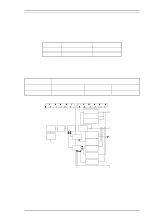
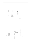
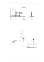
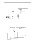
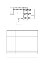
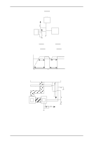
Operation Principles 5. +35 V Line Over Current Protection Circuit The +35 V line over current control circuit is illustrated below. R54 LQ-2070 Servcie Manual +35V Line 6 Q31 5 R70 R72 D85 Q53 R71 R73 GND C57 R74 R75 3 Q54 4 R68 Q82 PSC Figure 2-27 +35 V Line Over Current Protection Circuit When the +35 V line becomes less than 27 V, Q82 and Q54 turn on, and PC1 turns on. Consequently, Q32 and Q31 turn off, and then switching FET Q1 shuts off. When the protection circuit operates, this protection can only be removed by turning the power off and on again. 6. +5 V Line Over Current Protect Circuit +5 V line over current control circuit is shown below. L51 Q51 R53 +35V Line +5v Line R61 R51 D51 8 R88 R64 R65 IC51 TL494CN GND - -2 R67 + 1 + Figure 2-28 +5 V Line Over Current Protection Circuit Port 2 of IC51 (TL494CN) monitors the +5 V line, and this protection circuit operates when the +5 V line goes below 4.75 V. When this circuit operates, port 8 signal output of the PWM pulse stops, and Q51 stops its switching operation. Consequently, the +5 V line stops generating. 2-20 Rev.A
-
 1
1 -
2
-
3
-
4
-
5
-
6
-
7
-
8
-
9
-
10
-
11
-
12
-
13
-
14
-
15
-
16
-
17
-
18
-
19
-
20
-
21
-
22
-
23
-
24
-
25
-
26
-
27
-
28
-
29
-
30
-
31
-
32
-
33
-
34
-
35
-
36
-
37
-
38
-
39
-
40
-
41
-
42
-
43
-
44
-
45
-
46
-
47
-
48
-
49
-
50
-
51
-
52
-
53
-
54
-
55
-
56
-
57
-
58
-
59
-
60
-
61
-
62
-
 63
63 -
 64
64 -
 65
65 -
 66
66 -
 67
67 -
 68
68 -
 69
69 -
 70
70 -
 71
71 -
 72
72 -
 73
73 -
74
-
75
-
76
-
77
-
78
-
79
-
80
-
81
-
82
-
83
-
84
-
85
-
86
-
87
-
88
-
89
-
90
-
91
-
92
-
93
-
94
-
95
-
96
-
97
-
98
-
99
-
100
-
101
-
102
-
103
-
104
-
105
-
106
-
107
-
108
-
109
-
110
-
111
-
112
-
113
-
114
-
115
-
116
-
117
-
118
-
119
-
120
-
121
-
122
-
123
-
124
-
125
-
126
-
127
-
128
-
129
-
130
-
131
-
132
-
133
-
134
-
135
-
136
-
137
-
138
-
139
-
140
-
141
-
142
-
143
-
144
-
145
-
146
-
147
-
148
-
149
-
150
-
151
-
152
-
153
-
154
-
155
-
156
-
157
-
158
-
159
-
160
-
161
-
162
-
163
-
164
-
165
 |
 |
