Epson 2070 Service Manual - Page 88
Removing the Platen Assembly, Releasing the Locks for the Bushings,
 |
UPC - 010343812277
View all Epson 2070 manuals
Add to My Manuals
Save this manual to your list of manuals |
Page 88 highlights
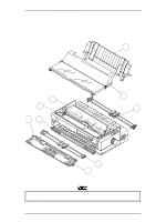
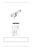
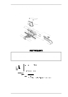
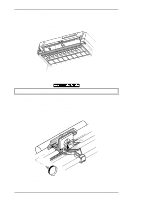
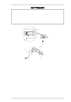
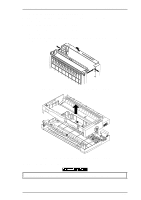
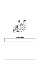
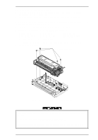
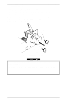
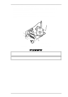
Disassembly and Assembly LQ-2070 Service Manual 3.2.6 Removing the Platen Assembly 1. Remove the printer cover, ribbon cartridge, and platen knob (see Section 3.2.1). 2. Release both locks for the left and right bushings (8 mm) by pushing the lever holder for the bushings outside, and then pulling the holder lever forward. Left and Right Bushings (8mm) Figure 3-11 Releasing the Locks for the Bushings 3 Slide the platen assembly to the right, and move the printhead to the right edge. 4. Pull the left edge of the platen assembly upward by tilting it backward, and then pull up the right edge of the platen assembly. Figure 3-12 Removing the Platen Assembly Assembly Notes Before reinstalling the platen assembly into the printer mechanism, move the printhead to the right edge of the CR shaft, and set the release lever to the tractor position. This pre-assembly operation helps you mount the platen assembly more easily. After installing the platen assembly into the printer mechanism, make sure both locks for left and right bushings (8 mm) are locked completely. Be careful handling the lever holders for the left and right bushings (8 mm). These are fragile. Adjust the platen gap. Refer to Chapter 4. 3-10 Rev.A
-
 1
1 -
2
-
3
-
4
-
5
-
6
-
7
-
8
-
9
-
10
-
11
-
12
-
13
-
14
-
15
-
16
-
17
-
18
-
19
-
20
-
21
-
22
-
23
-
24
-
25
-
26
-
27
-
28
-
29
-
30
-
31
-
32
-
33
-
34
-
35
-
36
-
37
-
38
-
39
-
40
-
41
-
42
-
43
-
44
-
45
-
46
-
47
-
48
-
49
-
50
-
51
-
52
-
53
-
54
-
55
-
56
-
57
-
58
-
59
-
60
-
61
-
62
-
63
-
64
-
65
-
66
-
67
-
68
-
69
-
70
-
71
-
72
-
73
-
74
-
75
-
76
-
77
-
78
-
79
-
80
-
81
-
82
-
 83
83 -
 84
84 -
 85
85 -
 86
86 -
 87
87 -
 88
88 -
 89
89 -
 90
90 -
 91
91 -
 92
92 -
 93
93 -
94
-
95
-
96
-
97
-
98
-
99
-
100
-
101
-
102
-
103
-
104
-
105
-
106
-
107
-
108
-
109
-
110
-
111
-
112
-
113
-
114
-
115
-
116
-
117
-
118
-
119
-
120
-
121
-
122
-
123
-
124
-
125
-
126
-
127
-
128
-
129
-
130
-
131
-
132
-
133
-
134
-
135
-
136
-
137
-
138
-
139
-
140
-
141
-
142
-
143
-
144
-
145
-
146
-
147
-
148
-
149
-
150
-
151
-
152
-
153
-
154
-
155
-
156
-
157
-
158
-
159
-
160
-
161
-
162
-
163
-
164
-
165
 |
 |
