Epson 2070 Service Manual - Page 101
Removing the Rear PE Sensor Assembly
 |
UPC - 010343812277
View all Epson 2070 manuals
Add to My Manuals
Save this manual to your list of manuals |
Page 101 highlights
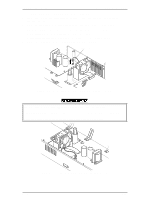
LQ-2070 Service Manual Disassembly and Assembly 3.2.9.8 Removing the Rear PE Sensor Assembly 1 Remove the rear/front edge guide assembly, front cover, paper eject assembly, rear/front tractor unit, and printer cover. 2. Remove the panel board (see Section 3.2.2) and upper housing assembly (see Section 3.2.7). 3. Remove the printer mechanism (see Section 3.2.9). 4. Turn the printer mechanism over, and insert a standard screwdriver or other prying tool into hole in the rear frame shown in the figure. 5. Release 2 clips while pushing up the rear PE sensor with the screwdriver or other prying tool. Rear PE Sensor Assembly 2 Clips Figure 3-33 Removing the Rear PE Sensor Assembly 6. Remove the rear PE sensor after disconnecting the connector. 3.2.9.9 Removing the Front PE Sensor Assembly 1. Remove the rear/front edge guide assembly, front cover, paper eject assembly, rear/front tractor unit, and printer cover. 2. Remove the panel board (see Section 3.2.2) and upper housing assembly (see Section 3.2.7). 3. Remove the printer mechanism (see Section 3.2.9). 4. Turn the printer mechanism over on the reverse side and remove the front PE sensor by pushing and releasing the 2 clips. Front PE Sensor Assembly Figure 3-34 Removing the Front PE Sensor Assembly Rev.A 3-23
-
 1
1 -
2
-
3
-
4
-
5
-
6
-
7
-
8
-
9
-
10
-
11
-
12
-
13
-
14
-
15
-
16
-
17
-
18
-
19
-
20
-
21
-
22
-
23
-
24
-
25
-
26
-
27
-
28
-
29
-
30
-
31
-
32
-
33
-
34
-
35
-
36
-
37
-
38
-
39
-
40
-
41
-
42
-
43
-
44
-
45
-
46
-
47
-
48
-
49
-
50
-
51
-
52
-
53
-
54
-
55
-
56
-
57
-
58
-
59
-
60
-
61
-
62
-
63
-
64
-
65
-
66
-
67
-
68
-
69
-
70
-
71
-
72
-
73
-
74
-
75
-
76
-
77
-
78
-
79
-
80
-
81
-
82
-
83
-
84
-
85
-
86
-
87
-
88
-
89
-
90
-
91
-
92
-
93
-
94
-
95
-
 96
96 -
 97
97 -
 98
98 -
 99
99 -
 100
100 -
 101
101 -
 102
102 -
 103
103 -
 104
104 -
 105
105 -
 106
106 -
107
-
108
-
109
-
110
-
111
-
112
-
113
-
114
-
115
-
116
-
117
-
118
-
119
-
120
-
121
-
122
-
123
-
124
-
125
-
126
-
127
-
128
-
129
-
130
-
131
-
132
-
133
-
134
-
135
-
136
-
137
-
138
-
139
-
140
-
141
-
142
-
143
-
144
-
145
-
146
-
147
-
148
-
149
-
150
-
151
-
152
-
153
-
154
-
155
-
156
-
157
-
158
-
159
-
160
-
161
-
162
-
163
-
164
-
165
 |
 |
