Epson 2070 Service Manual - Page 48

List of s, List of Tables

Page 48 highlights

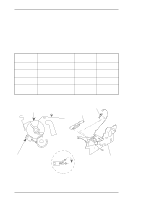
List of Figures Figure 2-1. Principles of Printhead Operation 2-1 Figure 2-2. Carriage Movement Mechanism 2-2 Figure 2-3. Platen Gap Adjust Lever 2-3 Figure 2-4. Release Sensor Switches 2-4 Figure 2-5. Friction Advance Operation Using the Top Entrance 2-5 Figure 2-6. Push Tractor Operation Using the Rear Paper Entrance 2-6 Figure 2-7. Push Tractor Operation Using the Front Paper Entrance 2-7 Figure 2-8. Pull Tractor Operation Using the Bottom Paper Entrance 2-8 Figure 2-9. Push- Pull Tractor Operation Using the Rear Paper Entrance . . . . . 2-9 Figure 2-10. Push- Pull Tractor Operation Using the Front Paper Entrance . . 2-10 Figure 2-11. Paper Path and Detector PE Sensor Location 2-11 Figure 2-12. Friction Feeding Using the Top Entrance 2-11 Figure 2-13. Push Tractor Feeding Using the Rear Entrance 2-12 Figure 2-14. Pull Tractor Feeding Using the Rear Entrance 2-12 Figure 2-15. Push-Pull Tractor Feeding Using the Rear Entrance 2-13 Figure 2-16. Pull Tractor Feeding Using the Bottom Entrance 2-13 Figure 2-17. Friction Feeding Using the Front Entrance 2-14 Figure 2-18. Push Tractor Feeding Using the Front Entrance 2-14 Figure 2-19. Pull Tractor Feeding Using the Front Entrance 2-15 Figure 2-20. Push-Pull Tractor Feeding Using the Front Entrance 2-15 Figure 2-21. Ribbon Advance Mechanism 2-16 Figure 2-22. Power Supply Circuit Block Diagram 2-17 Figure 2-23 Power Switch Circuit 2-18 Figure 2-24. Over Voltage Protection Circuit 2-18 Figure 2-25. +35 V Line Constant Voltage Control Circuit 2-19 Figure 2-26. +35 V Line Overload Detector Circuit 2-19 Figure 2-27. +35 V Line Over Current Protection Circuit 2-20 Figure 2-28. +5 V Line Over Current Protection Circuit 2-20 Figure 2-29. +5 V Constant Voltage Control Circuit 2-21 Figure 2-30. Control Circuit Block Diagram 2-22 Figure 2-31. Data Flow 2-23 Figure 2-32. Reset Circuit 2-24 Figure 2-33. Reset Signal Output Timing 2-24 Figure 2-34. Printhead Driver Circuit 2-24 Figure 2-35. CR Driver Circuit 2-25 Figure 2-36. PF Motor Driver Circuit 2-26 Figure 2-37. EEPROM Control Circuit 2-26 Figure 2-38. Sensor Circuit 2-27 List of Tables Table 2-1. CR Motor Assembly Specifications 2-2 Table 2-2. Platen Gap and Print Speed 2-3 Table 2-3. Release Lever Position 2-4 Table 2-4. Ribbon Advance Gear Linkage 2-16 Table 2-5. Power Supply Board 2-17 Table 2-6. Power Supply Output Voltage and Applications 2-17 Table 2-7. Functions of the Main IC 2-23 Table 2-8. CR Motor Driver Mode 2-25

  • 1
  • 2
  • 3
  • 4
  • 5
  • 6
  • 7
  • 8
  • 9
  • 10
  • 11
  • 12
  • 13
  • 14
  • 15
  • 16
  • 17
  • 18
  • 19
  • 20
  • 21
  • 22
  • 23
  • 24
  • 25
  • 26
  • 27
  • 28
  • 29
  • 30
  • 31
  • 32
  • 33
  • 34
  • 35
  • 36
  • 37
  • 38
  • 39
  • 40
  • 41
  • 42
  • 43
  • 44
  • 45
  • 46
  • 47
  • 48
  • 49
  • 50
  • 51
  • 52
  • 53
  • 54
  • 55
  • 56
  • 57
  • 58
  • 59
  • 60
  • 61
  • 62
  • 63
  • 64
  • 65
  • 66
  • 67
  • 68
  • 69
  • 70
  • 71
  • 72
  • 73
  • 74
  • 75
  • 76
  • 77
  • 78
  • 79
  • 80
  • 81
  • 82
  • 83
  • 84
  • 85
  • 86
  • 87
  • 88
  • 89
  • 90
  • 91
  • 92
  • 93
  • 94
  • 95
  • 96
  • 97
  • 98
  • 99
  • 100
  • 101
  • 102
  • 103
  • 104
  • 105
  • 106
  • 107
  • 108
  • 109
  • 110
  • 111
  • 112
  • 113
  • 114
  • 115
  • 116
  • 117
  • 118
  • 119
  • 120
  • 121
  • 122
  • 123
  • 124
  • 125
  • 126
  • 127
  • 128
  • 129
  • 130
  • 131
  • 132
  • 133
  • 134
  • 135
  • 136
  • 137
  • 138
  • 139
  • 140
  • 141
  • 142
  • 143
  • 144
  • 145
  • 146
  • 147
  • 148
  • 149
  • 150
  • 151
  • 152
  • 153
  • 154
  • 155
  • 156
  • 157
  • 158
  • 159
  • 160
  • 161
  • 162
  • 163
  • 164
  • 165

List of Figures
Figure 2-1. Principles of Printhead Operation . . . . . . . . . . . . . . . . . . . . . . . . . . .
2-1
Figure 2-2. Carriage Movement Mechanism . . . . . . . . . . . . . . . . . . . . . . . . . . . .
2-2
Figure 2-3. Platen Gap Adjust Lever . . . . . . . . . . . . . . . . . . . . . . . . . . . . . . . . . .
2-3
Figure 2-4. Release Sensor Switches . . . . . . . . . . . . . . . . . . . . . . . . . . . . . . . . .
2-4
Figure 2-5. Friction Advance Operation Using the Top Entrance . . . . . . . . . . . .
2-5
Figure 2-6. Push Tractor Operation Using the Rear Paper Entrance . . . . . . . . .
2-6
Figure 2-7. Push Tractor Operation Using the Front Paper Entrance. . . . . . . . .
2-7
Figure 2-8. Pull Tractor Operation Using the Bottom Paper Entrance
. . . . . . . .
2-8
Figure 2-9. Push- Pull Tractor Operation Using the Rear Paper Entrance . . . . .
2-9
Figure 2-10. Push- Pull Tractor Operation Using the Front Paper Entrance
. . 2-10
Figure 2-11. Paper Path and Detector PE Sensor Location . . . . . . . . . . . . . . .
2-11
Figure 2-12. Friction Feeding Using the Top Entrance . . . . . . . . . . . . . . . . . . .
2-11
Figure 2-13. Push Tractor Feeding Using the Rear Entrance. . . . . . . . . . . . . .
2-12
Figure 2-14. Pull Tractor Feeding Using the Rear Entrance . . . . . . . . . . . . . . .
2-12
Figure 2-15. Push-Pull Tractor Feeding Using the Rear Entrance . . . . . . . . . .
2-13
Figure 2-16. Pull Tractor Feeding Using the Bottom Entrance . . . . . . . . . . . . .
2-13
Figure 2-17. Friction Feeding Using the Front Entrance . . . . . . . . . . . . . . . . . .
2-14
Figure 2-18. Push Tractor Feeding Using the Front Entrance
. . . . . . . . . . . . .
2-14
Figure 2-19. Pull Tractor Feeding Using the Front Entrance
. . . . . . . . . . . . . .
2-15
Figure 2-20. Push-Pull Tractor Feeding Using the Front Entrance. . . . . . . . . .
2-15
Figure 2-21. Ribbon Advance Mechanism
. . . . . . . . . . . . . . . . . . . . . . . . . . . .
2-16
Figure 2-22. Power Supply Circuit Block Diagram
. . . . . . . . . . . . . . . . . . . . . .
2-17
Figure 2-23
Power Switch Circuit . . . . . . . . . . . . . . . . . . . . . . . . . . . . . . . . . . .
2-18
Figure 2-24. Over Voltage Protection Circuit
. . . . . . . . . . . . . . . . . . . . . . . . . .
2-18
Figure 2-25. +35 V Line Constant Voltage Control Circuit
. . . . . . . . . . . . . . . .
2-19
Figure 2-26. +35 V Line Overload Detector Circuit . . . . . . . . . . . . . . . . . . . . . .
2-19
Figure 2-27. +35 V Line Over Current Protection Circuit
. . . . . . . . . . . . . . . . .
2-20
Figure 2-28. +5 V Line Over Current Protection Circuit
. . . . . . . . . . . . . . . . . .
2-20
Figure 2-29. +5 V Constant Voltage Control Circuit
. . . . . . . . . . . . . . . . . . . . .
2-21
Figure 2-30. Control Circuit Block Diagram. . . . . . . . . . . . . . . . . . . . . . . . . . . .
2-22
Figure 2-31. Data Flow
. . . . . . . . . . . . . . . . . . . . . . . . . . . . . . . . . . . . . . . . . . .
2-23
Figure 2-32. Reset Circuit . . . . . . . . . . . . . . . . . . . . . . . . . . . . . . . . . . . . . . . . .
2-24
Figure 2-33. Reset Signal Output Timing
. . . . . . . . . . . . . . . . . . . . . . . . . . . . .
2-24
Figure 2-34. Printhead Driver Circuit. . . . . . . . . . . . . . . . . . . . . . . . . . . . . . . . .
2-24
Figure 2-35. CR Driver Circuit . . . . . . . . . . . . . . . . . . . . . . . . . . . . . . . . . . . . . .
2-25
Figure 2-36. PF Motor Driver Circuit . . . . . . . . . . . . . . . . . . . . . . . . . . . . . . . . .
2-26
Figure 2-37. EEPROM Control Circuit. . . . . . . . . . . . . . . . . . . . . . . . . . . . . . . .
2-26
Figure 2-38. Sensor Circuit . . . . . . . . . . . . . . . . . . . . . . . . . . . . . . . . . . . . . . . .
2-27
List of Tables
Table 2-1. CR Motor Assembly Specifications
. . . . . . . . . . . . . . . . . . . . . . . . . .
2-2
Table 2-2. Platen Gap and Print Speed
. . . . . . . . . . . . . . . . . . . . . . . . . . . . . . .
2-3
Table 2-3. Release Lever Position
. . . . . . . . . . . . . . . . . . . . . . . . . . . . . . . . . . .
2-4
Table 2-4. Ribbon Advance Gear Linkage
. . . . . . . . . . . . . . . . . . . . . . . . . . . .
2-16
Table 2-5. Power Supply Board
. . . . . . . . . . . . . . . . . . . . . . . . . . . . . . . . . . . .
2-17
Table 2-6. Power Supply Output Voltage and Applications
. . . . . . . . . . . . . . .
2-17
Table 2-7. Functions of the Main IC
. . . . . . . . . . . . . . . . . . . . . . . . . . . . . . . . .
2-23
Table 2-8. CR Motor Driver Mode . . . . . . . . . . . . . . . . . . . . . . . . . . . . . . . . . . .
2-25