Epson 2070 Service Manual - Page 75
Sensor Circuits, Sensor Circuit, sensor. The PW sensor
 |
UPC - 010343812277
View all Epson 2070 manuals
Add to My Manuals
Save this manual to your list of manuals |
Page 75 highlights
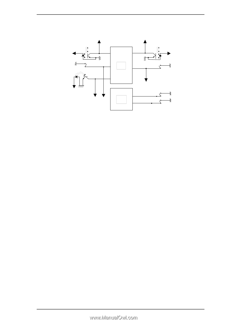
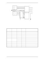
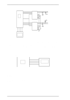
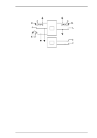
LQ-2070 Service Manual Operating Principles 2.3.7 Sensor Circuits The CPU detects conditions of the following sensors: home position (HP) sensor, release sensors 1 and 2, platen gap (PG) sensor, rear and front paper end (PE) sensors, paper width (PW) sensor. +5V +5V +5V Rear PE Sensor Front PE Sensor PW Sensor +5V 70 P40 76 P53 68 P36 CPU P27 61 75 AN2 +5V +5V +5V R2 6 8 Gate Array R1 6 7 Figure 2-38 Sensor Circuit +5V HP Sensor PG Sensor Release Sensor 2 Release Sensor 1 Two types of sensors are used in this printer. Release sensors 1 and 2, the PG sensors, and the front PE sensor are momentary switches. Pages 2-3 and 2-4 describe the relationship between release and PG sensor operation and actual print operation. The HP sensor, rear PE sensor, and PW sensor are photo diode switches. The HP sensor detects CR home position when the photo diode rays are cut off by the printhead. The rear PE sensor detects that paper has been loaded when the photo diode rays are cut off by the sensor plate, which is included in the rear PE sensor. The PW sensor, used for paper width measurement and paper loading positioning, detects the paper edge by comparing the voltage it measures with a standard voltage that was measured during the power on sequence. Additionally, as mentioned on the page 2-24, the +35 V line and head temperatures are monitored to set the pulse length of the head driver signal. Rev.A 2-27
-
 1
1 -
2
-
3
-
4
-
5
-
6
-
7
-
8
-
9
-
10
-
11
-
12
-
13
-
14
-
15
-
16
-
17
-
18
-
19
-
20
-
21
-
22
-
23
-
24
-
25
-
26
-
27
-
28
-
29
-
30
-
31
-
32
-
33
-
34
-
35
-
36
-
37
-
38
-
39
-
40
-
41
-
42
-
43
-
44
-
45
-
46
-
47
-
48
-
49
-
50
-
51
-
52
-
53
-
54
-
55
-
56
-
57
-
58
-
59
-
60
-
61
-
62
-
63
-
64
-
65
-
66
-
67
-
68
-
69
-
 70
70 -
 71
71 -
 72
72 -
 73
73 -
 74
74 -
 75
75 -
 76
76 -
 77
77 -
 78
78 -
 79
79 -
 80
80 -
81
-
82
-
83
-
84
-
85
-
86
-
87
-
88
-
89
-
90
-
91
-
92
-
93
-
94
-
95
-
96
-
97
-
98
-
99
-
100
-
101
-
102
-
103
-
104
-
105
-
106
-
107
-
108
-
109
-
110
-
111
-
112
-
113
-
114
-
115
-
116
-
117
-
118
-
119
-
120
-
121
-
122
-
123
-
124
-
125
-
126
-
127
-
128
-
129
-
130
-
131
-
132
-
133
-
134
-
135
-
136
-
137
-
138
-
139
-
140
-
141
-
142
-
143
-
144
-
145
-
146
-
147
-
148
-
149
-
150
-
151
-
152
-
153
-
154
-
155
-
156
-
157
-
158
-
159
-
160
-
161
-
162
-
163
-
164
-
165
 |
 |