Epson 2070 Service Manual - Page 124
Table 5-2 Sensor Test Points, Test Pin, Number, Test Method, Set Meter to DC Voltage., Troubleshooting
 |
UPC - 010343812277
View all Epson 2070 manuals
Add to My Manuals
Save this manual to your list of manuals |
Page 124 highlights
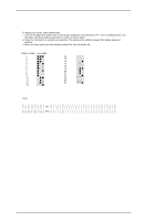
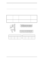
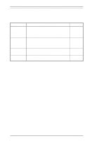
Troubleshooting LQ-2070 Service Manual 5.2.2 Sensors Table 5-2 Sensor Test Points Sensor Connector Number CN4 (HP Sensor) ^ ^ CN5 (Rear PE Sensor) ^ ^ CN6 (Front PE Sensor) ^ CN13 (PG Sensors ) ^ CN12 (Release Sensor 1) ^ CN16 (Release Snesor 2) ^ CN7 (PW Sensor) ^ ^ ^ Test Pin Number 1: HP 2: GND 3: +5 V 1: +5 V 2: PE 3: GND 1: PE 2: GND 1: PG 1 2: GND 1: Release 1 2: GND 1: Release 2 2: GND 1: E 2: GND 3: +5 V 4: A Test Method (Set Meter to DC Voltage. ) Meter Reading Place one lead on pin 1 and the other lead on pin 2, and check the voltage while blocking the two sensor terminals. Open: +5 V (Home position) Short: 0 V (Not home) ^ ^ Place one lead on pin 2 and the other lead on pin 3, and check the voltage while toggling the sensor lever. Open: +5 V (Paper loaded) Short: 0 V (No paper) ^ ^ Place one lead on pin 1 and the other lead on pin 2, and check the voltage while toggling the sensor lever. Open : +5 V (Paper loaded) Short: 0 V (No paper) Place one lead on pin 1 and the other lead on pin 2 and check the voltage while toggling the sensor lever. ^ Open: +5 V Short: 0 V ^ Place one lead on pin1 and other lead on pin 2 and chaeck the voltage while toggling the sensor lever. Open: +5V Short: 0V ^ Place one lead on pin1 and other lead on pin 2 and chaeck the voltage while toggling the sensor lever. Open: +5V Short: 0V ^ Place one lead on pin 1 and the other lead on pin 2, and check the voltage while inserting and removing paper between the platen and sensor. 0 < Open Voltage (No paper) < Short Voltage (Paper loaded) ^ ^ ^ 5-2 Rev. A
-
 1
1 -
2
-
3
-
4
-
5
-
6
-
7
-
8
-
9
-
10
-
11
-
12
-
13
-
14
-
15
-
16
-
17
-
18
-
19
-
20
-
21
-
22
-
23
-
24
-
25
-
26
-
27
-
28
-
29
-
30
-
31
-
32
-
33
-
34
-
35
-
36
-
37
-
38
-
39
-
40
-
41
-
42
-
43
-
44
-
45
-
46
-
47
-
48
-
49
-
50
-
51
-
52
-
53
-
54
-
55
-
56
-
57
-
58
-
59
-
60
-
61
-
62
-
63
-
64
-
65
-
66
-
67
-
68
-
69
-
70
-
71
-
72
-
73
-
74
-
75
-
76
-
77
-
78
-
79
-
80
-
81
-
82
-
83
-
84
-
85
-
86
-
87
-
88
-
89
-
90
-
91
-
92
-
93
-
94
-
95
-
96
-
97
-
98
-
99
-
100
-
101
-
102
-
103
-
104
-
105
-
106
-
107
-
108
-
109
-
110
-
111
-
112
-
113
-
114
-
115
-
116
-
117
-
118
-
 119
119 -
 120
120 -
 121
121 -
 122
122 -
 123
123 -
 124
124 -
 125
125 -
 126
126 -
 127
127 -
 128
128 -
 129
129 -
130
-
131
-
132
-
133
-
134
-
135
-
136
-
137
-
138
-
139
-
140
-
141
-
142
-
143
-
144
-
145
-
146
-
147
-
148
-
149
-
150
-
151
-
152
-
153
-
154
-
155
-
156
-
157
-
158
-
159
-
160
-
161
-
162
-
163
-
164
-
165
 |
 |
