Epson 2070 Service Manual - Page 52
Paper Handling Mechanisms, Table 2-3. Release Lever Position, Release Switch
 |
UPC - 010343812277
View all Epson 2070 manuals
Add to My Manuals
Save this manual to your list of manuals |
Page 52 highlights
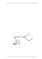
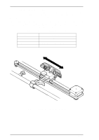
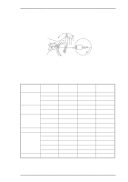
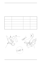
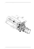
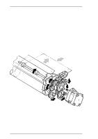
Operation Principles LQ-2070 Servcie Manual 2.1.4. Paper Handling Mechanisms During normal operation, paper is fed into the printer, advanced to the specified position, and then ejected from the printer. These paper-handling operations are performed by various paper handling mechanisms, such as tractors, platens, rollers, and gears. This section describes the printer's paper handling mechanisms. 2.1.4.1. Release Lever The release lever is used to select friction for rear/front tractor feed or to release the paper for pull tractor feed. Changing the release lever position moves the paper guide rollers, and the new lever position is detected by 2 release switch sensors (RLSW1 and RLSW2). See the following table. The RLSW1 sensor is located on the left side frame and the RLSW2 sensor is located on the inside of the right sub frame. Refer to Figure 2-4. Table 2-3. Release Lever Position Release Lever Position Friction mode Rear push tractor mode Front push tractor mode Pull tractor mode Status of Paper Guide Rollers The paper guide rollers are pressed against the platen The paper guide rollers are separated from the platen The paper guide rollers are separated from the platen The paper guide rollers and the rollers for the lower paper guide are separated from each other. RLSW1 Open Closed Closed Closed RLSW2 Open Open Open Closed Platen Left Frame Lelease SW2 Tractor Clutch Cam Release SW1 2-4 Open Close Figure 2-4 Release Switch Right Sub Fram Rev.A
-
 1
1 -
2
-
3
-
4
-
5
-
6
-
7
-
8
-
9
-
10
-
11
-
12
-
13
-
14
-
15
-
16
-
17
-
18
-
19
-
20
-
21
-
22
-
23
-
24
-
25
-
26
-
27
-
28
-
29
-
30
-
31
-
32
-
33
-
34
-
35
-
36
-
37
-
38
-
39
-
40
-
41
-
42
-
43
-
44
-
45
-
46
-
 47
47 -
 48
48 -
 49
49 -
 50
50 -
 51
51 -
 52
52 -
 53
53 -
 54
54 -
 55
55 -
 56
56 -
 57
57 -
58
-
59
-
60
-
61
-
62
-
63
-
64
-
65
-
66
-
67
-
68
-
69
-
70
-
71
-
72
-
73
-
74
-
75
-
76
-
77
-
78
-
79
-
80
-
81
-
82
-
83
-
84
-
85
-
86
-
87
-
88
-
89
-
90
-
91
-
92
-
93
-
94
-
95
-
96
-
97
-
98
-
99
-
100
-
101
-
102
-
103
-
104
-
105
-
106
-
107
-
108
-
109
-
110
-
111
-
112
-
113
-
114
-
115
-
116
-
117
-
118
-
119
-
120
-
121
-
122
-
123
-
124
-
125
-
126
-
127
-
128
-
129
-
130
-
131
-
132
-
133
-
134
-
135
-
136
-
137
-
138
-
139
-
140
-
141
-
142
-
143
-
144
-
145
-
146
-
147
-
148
-
149
-
150
-
151
-
152
-
153
-
154
-
155
-
156
-
157
-
158
-
159
-
160
-
161
-
162
-
163
-
164
-
165
 |
 |
