Epson 2070 Service Manual - Page 82
PRINTER DISASSEMBLY AND ASSEMBLY, Flowchart for Disassembling the Printer
 |
UPC - 010343812277
View all Epson 2070 manuals
Add to My Manuals
Save this manual to your list of manuals |
Page 82 highlights
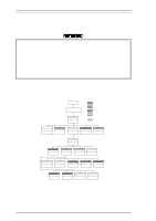
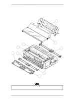
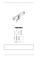
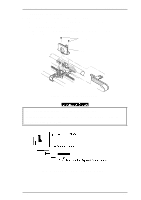
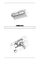
Disassembly and Assembly LQ-2070 Service Manual 3.2. PRINTER DISASSEMBLY AND ASSEMBLY This section describes procedures for disassembling and assembling the main components of the printer. When the procedure for installing a component is simply the reverse of removing the component, this chapter does not describe the assembly procedure. If necessary, special notes on assembling or adjusting a component are given at the end of the description of each procedure. Be sure to follow the instructions in these notes. CAUTION • Before disassembling any part of the printer, note the warnings in Section 3.1. • Before beginning to disassemble the printer, remove the paper and the ink ribbon. Also disconnect the interface cable. • Whenever the printer is repaired, wipe the surface of the paper width (PW) sensor assembly with a soft cloth, and keep it clean to avoid abnormal operation. If the surface is dirty from any adhering material, sensor sensitivity goes down and operation is not correct. • Be careful operating the release lever. Frequent operation of the release lever back and forth without the upper housing cover may cause damage to the lever or dislocation of the engagement. Note: Exploded diagrams in the appendix show you how the components fit together. Refer to them as necessary. The flowchart below shows the order you need to use to disassemble the printer. For details of the required adjustments, refer to Chapter 4. START Disconnect power cord and I/F cable. 3.2.1 Page 3-5 Before Starting Disassembly Bidirectional adjustment required. PG adjustment required. Bidirectional and PG adjustment required. Bidirectional adjustment and factory setting required (when part is replaced). TPE level reset required (when part is replaced). 3.2.2 Page 3-6 Removing the Panel Board Assembly 3.2.3 Page 3-7 Removing the Printhead 3.2.4 Page 3-8 Removing the HP Sensor 3.2.5 Page 3-8 Removing the PW Sensor 3.2.6 Page 3-10 Removing the Platen Assembly 3.2.7 Page 3-11 Removing the Upper Housing Assembly 3.2.8 Page 3-12 Removing the CR Motor Assembly 3.2.9 Page 3-13 Removing the Printer Mechanism 3.2.10 Page 3-24 Removing the C186 MAIN Board 3.2.11 Page 3-25 Removing the C166 PSB/E Board 3.2.9.1 Page 3-14 Removing the PF Motor Assembly 3.2.9.2 Page 3-15 Removing the PG Sensor 3.2.9.3 Page 3-16 Removing the Right Frame Assembly 3.2.9.4 Page 3-16 Disassembling the Right Sub Frame 3.2.9.5 Page 3-19 Removing the Left Frame Assembly 3.2.9.6 Page 3-20 Removing the RD Assembly 3.2.9.7 Page 3-21 Removing the CR Assembly 3.2.9.8 Page 3-23 Removing the Rear PE Sensor 3.2.9.9 Page 3-23 Removing the Front PE Sensor Figure 3-2 Flowchart for Disassembling the Printer 3-4 Rev.A
-
 1
1 -
2
-
3
-
4
-
5
-
6
-
7
-
8
-
9
-
10
-
11
-
12
-
13
-
14
-
15
-
16
-
17
-
18
-
19
-
20
-
21
-
22
-
23
-
24
-
25
-
26
-
27
-
28
-
29
-
30
-
31
-
32
-
33
-
34
-
35
-
36
-
37
-
38
-
39
-
40
-
41
-
42
-
43
-
44
-
45
-
46
-
47
-
48
-
49
-
50
-
51
-
52
-
53
-
54
-
55
-
56
-
57
-
58
-
59
-
60
-
61
-
62
-
63
-
64
-
65
-
66
-
67
-
68
-
69
-
70
-
71
-
72
-
73
-
74
-
75
-
76
-
 77
77 -
 78
78 -
 79
79 -
 80
80 -
 81
81 -
 82
82 -
 83
83 -
 84
84 -
 85
85 -
 86
86 -
 87
87 -
88
-
89
-
90
-
91
-
92
-
93
-
94
-
95
-
96
-
97
-
98
-
99
-
100
-
101
-
102
-
103
-
104
-
105
-
106
-
107
-
108
-
109
-
110
-
111
-
112
-
113
-
114
-
115
-
116
-
117
-
118
-
119
-
120
-
121
-
122
-
123
-
124
-
125
-
126
-
127
-
128
-
129
-
130
-
131
-
132
-
133
-
134
-
135
-
136
-
137
-
138
-
139
-
140
-
141
-
142
-
143
-
144
-
145
-
146
-
147
-
148
-
149
-
150
-
151
-
152
-
153
-
154
-
155
-
156
-
157
-
158
-
159
-
160
-
161
-
162
-
163
-
164
-
165
 |
 |
