Epson 2070 Service Manual - Page 76

Disassembly and Assembly

Page 76 highlights

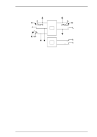
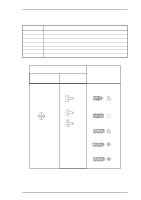
CHAPTER 3 Disassembly and Assembly Table of Contents 3.1 OVERVIEW 3-1 3.1.1 Precautions 3-1 3.1.2 Tools 3-1 3.1.3 Service Checks After Repair 3-2 3.1.4 Specifications for Screws 3-3 3.2 PRINTER DISASSEMBLY AND ASSEMBLY 3-4 3.2.1 Before Starting Disassembly Procedures 3-5 3.2.2 Removing the Panel Board Assembly 3-6 3.2.3 Removing the Printhead 3-7 3.2.4 Removing the HP Sensor 3-8 3.2.5 Removing the PW Sensor Assembly 3-8 3.2.6 Removing the Platen Assembly 3-10 3.2.7 Removing the Upper Housing Assembly 3-11 3.2.8 Removing the CR Motor Assembly 3-12 3.2.9 Removing the Printer Mechanism 3-13 3.2.9.1. Removing the PF Motor Assembly 3-14 3.2.9.2 Removing the PG Sensor Assembly 3-15 3.2.9.3 Removing the Right Frame Assembly 3-16 3.2.9.4. Disassembling the Right Frame Assembly 3-16 3.2.9.5. Removing the Left Frame Assembly 3-19 3.2.9.6 Removing the Ribbon Drive (RD) Assembly 3-20 3.2.9.7. Removing the CR Assembly 3-21 3.2.9.8 Removing the Rear PE Sensor Assembly 3-23 3.2.9.9 Removing the Front PE Sensor Assembly 3-23 3.2.10 Removing the C186 MAIN Board Assembly 3-24 3.2.11 Removing the C166 PSB/E Board Assembly 3-25 3.3 DISASSEMBLY AND ASSEMBLY OF CSF BIN 1 3-26 3.3.1 Disassembling the Right Side Block 3-26 3.3.2 Disassembling the Paper Support Block Assembly 3-28 3.3.3 Removing the Paper Eject Cover Assembly 3-30 3.4 DISASSEMBLY AND ASSEMBLY OF CSF BIN 2 3-31 3.4.1 Disassembly Right Side Block 3-31 3.4.2 Disassembly Paper Support Block Assembly 3-32

  • 1
  • 2
  • 3
  • 4
  • 5
  • 6
  • 7
  • 8
  • 9
  • 10
  • 11
  • 12
  • 13
  • 14
  • 15
  • 16
  • 17
  • 18
  • 19
  • 20
  • 21
  • 22
  • 23
  • 24
  • 25
  • 26
  • 27
  • 28
  • 29
  • 30
  • 31
  • 32
  • 33
  • 34
  • 35
  • 36
  • 37
  • 38
  • 39
  • 40
  • 41
  • 42
  • 43
  • 44
  • 45
  • 46
  • 47
  • 48
  • 49
  • 50
  • 51
  • 52
  • 53
  • 54
  • 55
  • 56
  • 57
  • 58
  • 59
  • 60
  • 61
  • 62
  • 63
  • 64
  • 65
  • 66
  • 67
  • 68
  • 69
  • 70
  • 71
  • 72
  • 73
  • 74
  • 75
  • 76
  • 77
  • 78
  • 79
  • 80
  • 81
  • 82
  • 83
  • 84
  • 85
  • 86
  • 87
  • 88
  • 89
  • 90
  • 91
  • 92
  • 93
  • 94
  • 95
  • 96
  • 97
  • 98
  • 99
  • 100
  • 101
  • 102
  • 103
  • 104
  • 105
  • 106
  • 107
  • 108
  • 109
  • 110
  • 111
  • 112
  • 113
  • 114
  • 115
  • 116
  • 117
  • 118
  • 119
  • 120
  • 121
  • 122
  • 123
  • 124
  • 125
  • 126
  • 127
  • 128
  • 129
  • 130
  • 131
  • 132
  • 133
  • 134
  • 135
  • 136
  • 137
  • 138
  • 139
  • 140
  • 141
  • 142
  • 143
  • 144
  • 145
  • 146
  • 147
  • 148
  • 149
  • 150
  • 151
  • 152
  • 153
  • 154
  • 155
  • 156
  • 157
  • 158
  • 159
  • 160
  • 161
  • 162
  • 163
  • 164
  • 165

CHAPTER 3
Disassembly and Assembly
Table of Contents
3.1
OVERVIEW
3-1
3.1.1
Precautions. . . . . . . . . . . . . . . . . . . . . . . . . . . . . . . . . . . . . . . . . . . . . . . . . 3-1
3.1.2
Tools . . . . . . . . . . . . . . . . . . . . . . . . . . . . . . . . . . . . . . . . . . . . . . . . . . . . . . 3-1
3.1.3
Service Checks After Repair
. . . . . . . . . . . . . . . . . . . . . . . . . . . . . . . . . . . 3-2
3.1.4
Specifications for Screws . . . . . . . . . . . . . . . . . . . . . . . . . . . . . . . . . . . . . . 3-3
3.2
PRINTER DISASSEMBLY AND ASSEMBLY
3-4
3.2.1
Before Starting Disassembly Procedures
. . . . . . . . . . . . . . . . . . . . . . . . . 3-5
3.2.2
Removing the Panel Board Assembly . . . . . . . . . . . . . . . . . . . . . . . . . . . . 3-6
3.2.3
Removing the Printhead . . . . . . . . . . . . . . . . . . . . . . . . . . . . . . . . . . . . . . . 3-7
3.2.4
Removing the HP Sensor . . . . . . . . . . . . . . . . . . . . . . . . . . . . . . . . . . . . . . 3-8
3.2.5
Removing the PW Sensor Assembly . . . . . . . . . . . . . . . . . . . . . . . . . . . . . 3-8
3.2.6
Removing the Platen Assembly . . . . . . . . . . . . . . . . . . . . . . . . . . . . . . . . 3-10
3.2.7
Removing the Upper Housing Assembly . . . . . . . . . . . . . . . . . . . . . . . . . 3-11
3.2.8
Removing the CR Motor Assembly
. . . . . . . . . . . . . . . . . . . . . . . . . . . . . 3-12
3.2.9
Removing the Printer Mechanism
. . . . . . . . . . . . . . . . . . . . . . . . . . . . . . 3-13
3.2.9.1. Removing the PF Motor Assembly
. . . . . . . . . . . . . . . . . . . . . . . 3-14
3.2.9.2
Removing the PG Sensor Assembly . . . . . . . . . . . . . . . . . . . . . . 3-15
3.2.9.3
Removing the Right Frame Assembly . . . . . . . . . . . . . . . . . . . . . 3-16
3.2.9.4. Disassembling the Right Frame Assembly
. . . . . . . . . . . . . . . . . 3-16
3.2.9.5. Removing the Left Frame Assembly . . . . . . . . . . . . . . . . . . . . . . 3-19
3.2.9.6
Removing the Ribbon Drive (RD) Assembly . . . . . . . . . . . . . . . . 3-20
3.2.9.7. Removing the CR Assembly . . . . . . . . . . . . . . . . . . . . . . . . . . . . 3-21
3.2.9.8
Removing the Rear PE Sensor Assembly. . . . . . . . . . . . . . . . . . 3-23
3.2.9.9
Removing the Front PE Sensor Assembly
. . . . . . . . . . . . . . . . . 3-23
3.2.10 Removing the C186 MAIN Board Assembly . . . . . . . . . . . . . . . . . . . . . . 3-24
3.2.11 Removing the C166 PSB/E Board Assembly . . . . . . . . . . . . . . . . . . . . . 3-25
3.3 DISASSEMBLY AND ASSEMBLY OF CSF BIN 1
3-26
3.3.1 Disassembling the Right Side Block . . . . . . . . . . . . . . . . . . . . . . . . . . . . . 3-26
3.3.2 Disassembling the Paper Support Block Assembly
. . . . . . . . . . . . . . . . . 3-28
3.3.3 Removing the Paper Eject Cover Assembly
. . . . . . . . . . . . . . . . . . . . . . 3-30
3.4 DISASSEMBLY AND ASSEMBLY OF CSF BIN 2
3-31
3.4.1 Disassembly Right Side Block. . . . . . . . . . . . . . . . . . . . . . . . . . . . . . . . . . 3-31
3.4.2 Disassembly Paper Support Block Assembly . . . . . . . . . . . . . . . . . . . . . . 3-32